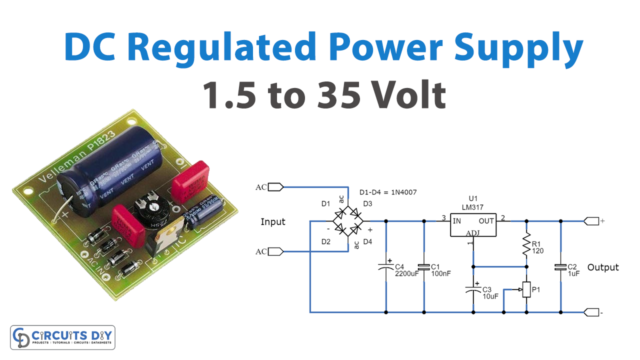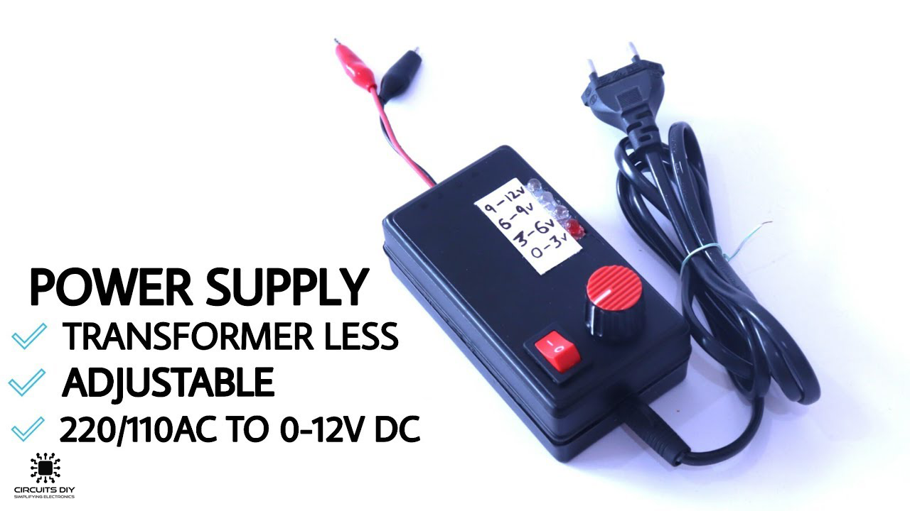
A Transformerless Adjustable Power Supply provides DC power for various tools such as test benches, electronic trainer boards, etc. The primary function of a Transformerless Adjustable Power Supply is to translate an input AC Signal to a required DC level. So, in this project, we are going to build a simple 220\110v AC TO 0-12V DC Transformer less Adjustable Power Supply Circuit Using LM317 linear voltage regulator IC & an X-rated capacitor.
Transformerless Power Supply?
A Transformerless power supply basically translates a high voltage AC into a desirable DC voltage without the use of a transformer. The main component of a Transformerless power supply circuit is a Voltage dropping capacitor or X-rated capacitor, which is specially designed for AC lines. They are sometimes connected Line to neutral in some circuits, which helps to block any electrical noise from entering the circuit.
JLCPCB is the foremost PCB prototype & manufacturing company in china, providing us with the best service we have ever experienced regarding (Quality, Price Service & Time).
Hardware Components
The following components are required to make Transformerless Power Supply
| S. No | Component | Value | Qty |
|---|---|---|---|
| 1. | Film Capacitor (ceramic) | 1.1uF/105J/400V | 1 |
| 2. | Bridge rectifier | IN4007 | 1 |
| 3. | Voltage regulator | LM317 | 1 |
| 4. | Rail connector | – | 1 |
| 5. | Zener diode | 12V/1W | 2 |
| 6. | LED | 5mm | 4 |
| 7. | Potentiometer | 10K | 1 |
| 8. | Capacitor | 47uF/63V | 1 |
| 9. | Resistors | 470K, 1K, 220 Ohm | 5 |
| 10. | Breadboard/Veroboard | – | 1 |
| 11. | Soldering Iron | 45W – 60W | 1 |
| 12. | Soldering wire with Flux | – | 1 |
| 13. | Connecting Wires | – | As per need |
LM317 Pinout
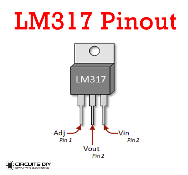
For a detailed description of pinout, dimension features, and specifications download the datasheet o LM317
Useful Steps
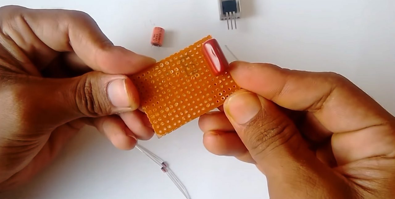
1) Solder the film capacitor onto the Veroboard.
2) Solder the 470K resistor & the bridge rectifier onto the Veroboard

3) Solder the two Zener diodes in series.

4) Solder the -ve terminal of the 47uF/63V capacitor to the anode of the Zener diode & the +ve terminal to the cathode.

5) Solder the LM317 voltage regulator to the +ve terminal of the 47uF capacitor, and solder the 1K resistor between the ADJ pin of the regulator & the Vout pin of the IC.
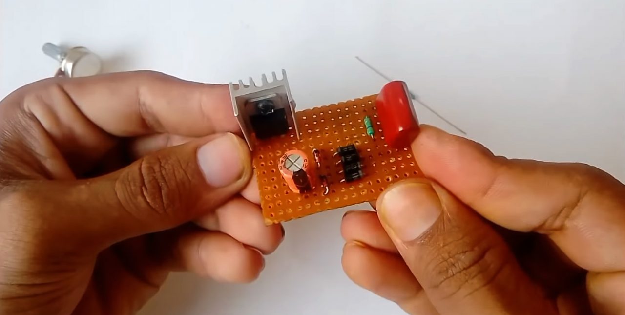
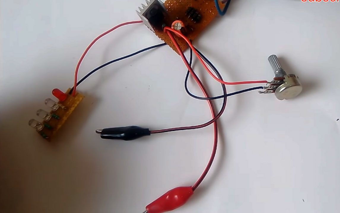
6) Solder the 10K pot between the -ve terminal of the capacitor & the ADJ pin of the regulator IC.
7) Solder crocodile clips on the -ve terminal of the 47uF capacitor & the Vout pin of the IC.

8) Solder one terminal of the wall plug with the film capacitor and cathode point of the bridge rectifier & other with the anode point of the bridge rectifier.
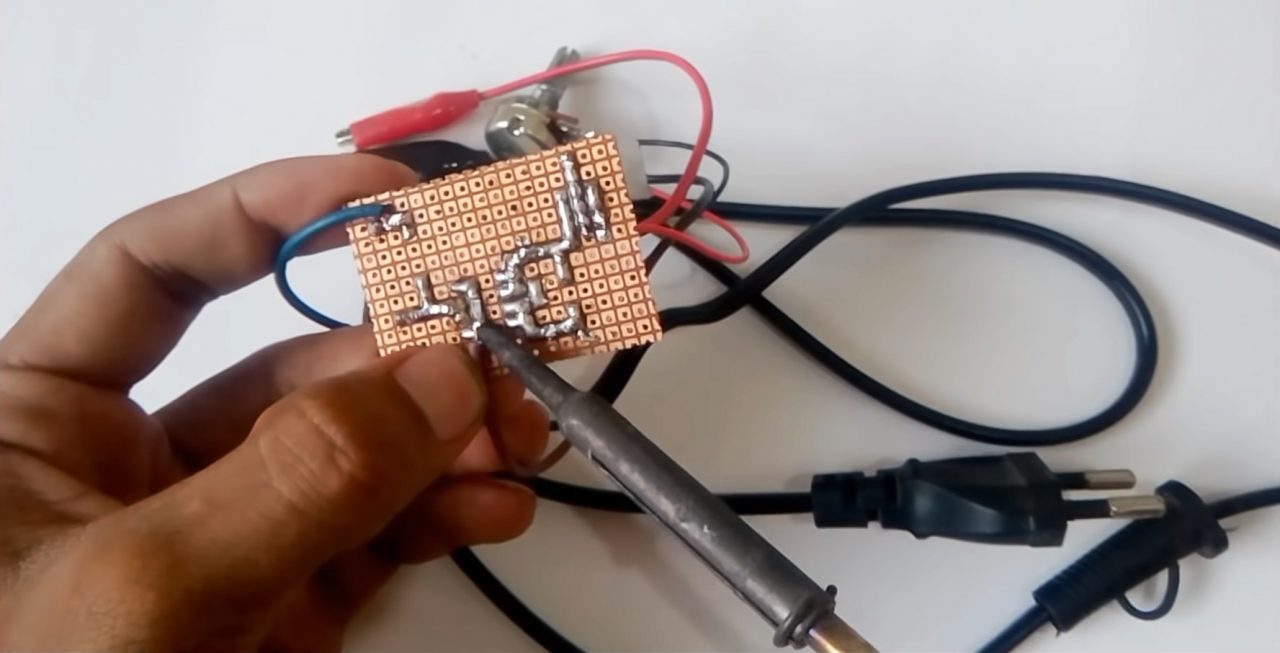
9) Check the output voltage using an AVO meter.

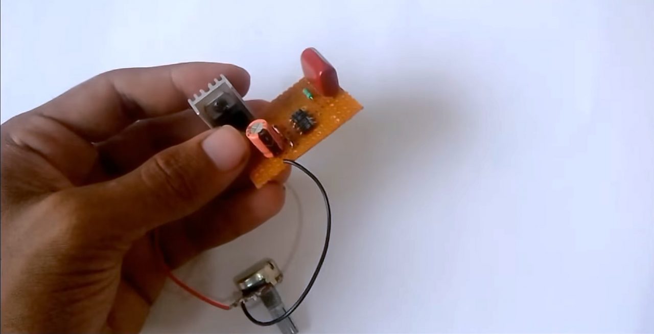
10) IC voltage indicator: Solder 4 LED in series with appropriate resistances.
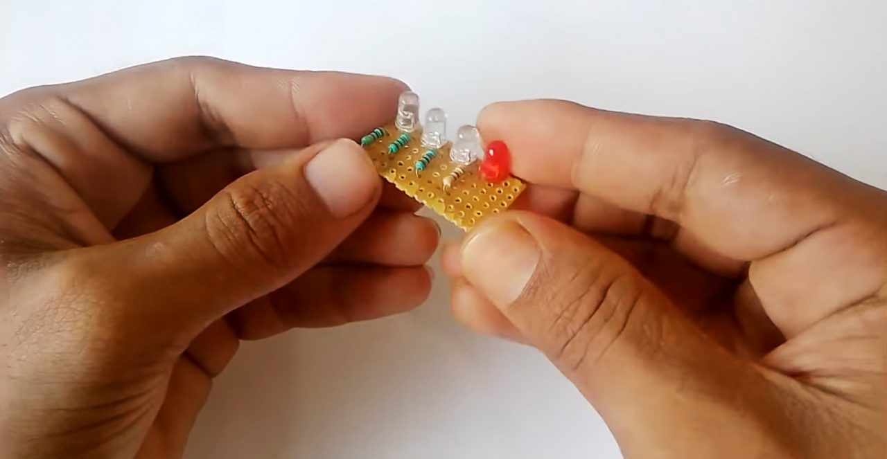
11) Solder the anode of the LEDs to the Vout of regulator IC & the cathode terminal to the -ve terminal of 47uF capacitor.
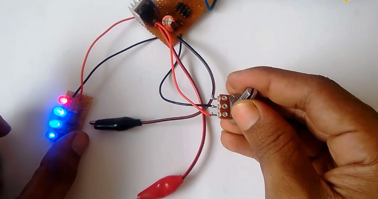
12) Test the circuit.
Working Explanation
The working of this circuit is as follows, an input supply of 220V AC is provided to the circuit. The X-rated capacitor (1.1uF) drops the voltage to the desired voltage range, here, A 470K Ohm resistor is connected in parallel to Capacitor, to discharge the stored current in the capacitor when the circuit is off, thus preventing electric shock. This resistance is called Bleeder resistance.
The low AC signal is then sent to a bridge rectifier (combination of 4 diodes) which converts the AC Signal into a rippling DC. After this, the out DC signal passes through two 12V/1W Zener diodes to achieve a noisy 12V output. The DC signal then passes through a smoothing capacitor (47uF) before moving on towards the LM317 voltage regulator which produces a constant DC output, here a 10K Ohm pot provides a voltage tuning option. Only use resistors with a wattage rating of 1W or higher otherwise the resistors might burn out after some time.
Applications
- DC Power supplies find their use in applications such as DC test benches, appliances & trainer equipment.
- Commonly used in testing small electronic projects.