Does the switch ever make you feel shocked? It usually does not happen, but often it can be hazardous to physically touch the switches. But What if you have to press a button on or off your home appliances, and the switch gets wireless? Today we are designing a simple wireless switch, whereby physical contact with the interrupter is not required. Only one has to take his hand over the switch, and it turns ON/OFF.
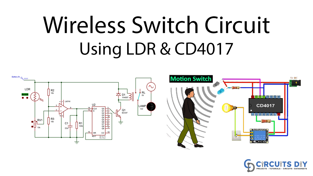
This tutorial leads the construction of a Wireless Switch Circuit using LDR and CD4017. Now, we’ll teach you in this project how to develop an LDR, LM741op-amp IC, and 4017 decades counter IC wireless circuit. When you first turn your hand to both the LDR, the lights change on, and the LDR switches off the light when you take your hand. We know that when light falls on it, resistance to LDR decreases and the LDR’s resistance increases if concealed in everything, which changes the LDR’s voltage.
Hardware Component
The following components are required to make Wireless Switch Circuit
| S.no | Component | Value | Qty |
|---|---|---|---|
| 1. | Bulb | – | 1 |
| 2. | LDR (Light Dependent Resistor) | – | 1 |
| 3. | Connecting wires | – | – |
| 4. | Potentiometer | 10k | 1 |
| 5. | Resistor | 10k | 1 |
| 6. | Relay module | 5v | 1 |
| 7. | Decade counter IC | CD4017 | 1 |
| 8. | Battery | 9v | 1 |
| 9. | Capacitor | 22uf | 1 |
| 10. | Op-amp IC | LM741 | 1 |
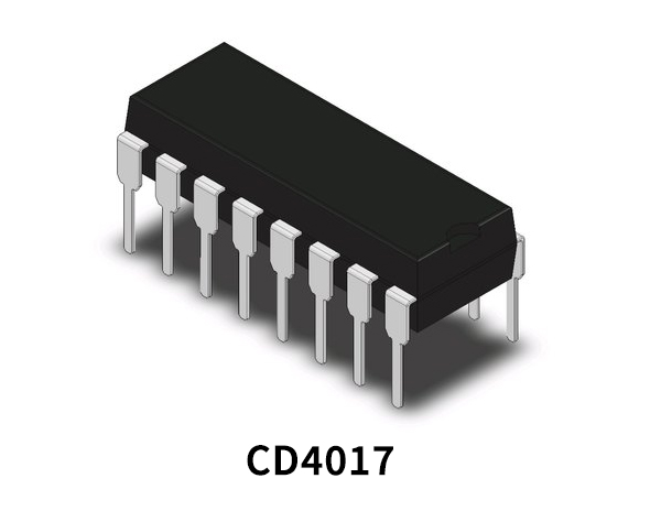
CD4017 Pinout
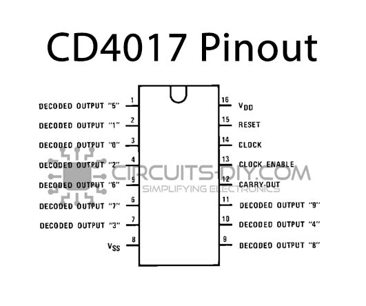
For a detailed description of pinout, dimension features, and specifications download the datasheet of CD4017
LM741 IC Pinout
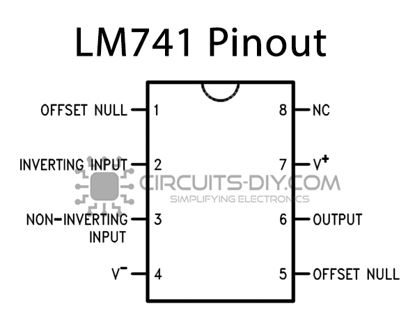
For a detailed description of pinout, dimension features, and specifications download the datasheet of LM741 IC
For a detailed description of pinout, dimension features, and specifications download the datasheet of NE555 IC
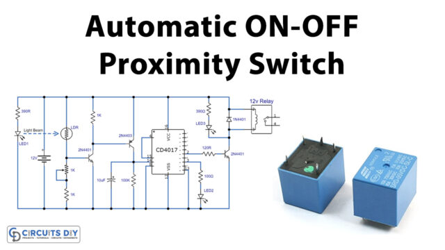
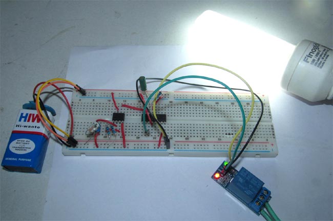
Wireless Switch Circuit

Circuit Operation
Initially, as we have a Relay to Q0 pin 4017 and Q0 is high in 4017 IC, the AC light will continue in the ON condition. Now, if someone first passes the hand over the LDR or covers it with a touch more resistance and the voltage at LM741 Pin3 is higher than Pin2, which leads to the output Pin 6 of op-amp 741 HIGH. The Op-amp output is connected to the IC 4017 counter clock PIN 14 of the Decade. As the OP-output amp becomes HIGH, the PIN to HIGH clock pulse is generated at 4017 IC, which generates IC 4017’s low output (PIN3) and pin two output (or Q10). Now the light switch before the next clock pulse is formed if we carry the hand over the LDR again.
The LM741 output remains high only until the light on the LDR is concealed, but once we remove the cap, LM741 output Pin 6 is again low. However, it does not affect 4017’s lockable efficiency, as IC 4017 only transfers its output to the next pin if it slowly gets too high fluctuations. Thus the high to low pressure created when the LM741 output is increased to low isn’t affected.
Apart from this, The production of the OP is yet again high when we go over the LDR, and IC 4017 is also given a low to high clock pulse, switching the Q1 from HIGH to LOW and getting the Q2 (PIN 4) high. The trick well we’ve now fed the excellent quality Q2 to IC4017’s Reset Pin 15, rebooting the IC and inserting the IC in the default Q0 mode. Light is switched on also at Q0 high
Applications and Uses
In this wireless transfer circuit, the LM741, when a hand passes over the LDR, is used to deliver a low to high clock pulse to IC 4017.