Introduction
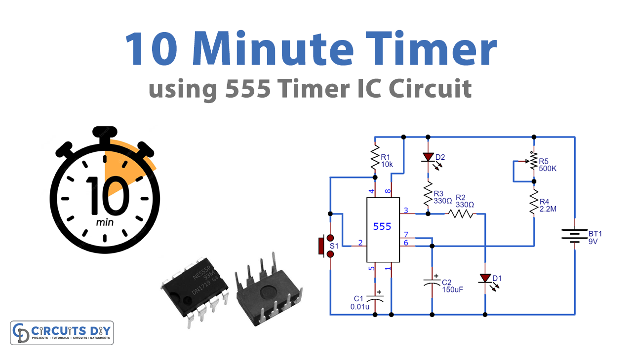
Since we are living in an era where we always take help from gadgets that make our life easy. Timer circuits make your day manageable by alerting you about the task to complete. This basic circuit is the alarm circuit that alerts the holder after 10 minutes. We can use numerous timer circuits having different time alerts, here in this project we are going to make a 10 minutes timer circuit that operates any device at the output as load, it can be a speaker, motor, etc, but we are using LED to explain our circuit.
NE555 is used for making this circuit, the IC works in a monostable mode in this project. The 555 timer IC is a beneficial and accurate timing component that provides a pulse of any particular duty cycle. The time durations are set by the potentiometer in the circuit.
Hardware Required
| S.no | Components | Value | Qty |
|---|---|---|---|
| 1. | Breadboard | – | 1 |
| 2. | IC Timer | NE555 | 1 |
| 3. | Resistor | 330, 10K, 2.2M | 2, 1, 1 |
| 4. | Capacitors | 0.01uF, 150uF | 1, 1 |
| 5. | LED | – | 1 |
| 6. | Potentiometer | 500K | 1 |
| 7. | Battery | 5V | 1 |
| 8. | Switch | – | 1 |
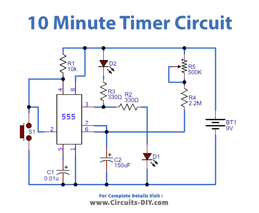
Circuit Diagram
Working Explanation
First, we need to build a timer IC as a monostable vibrator. When the switch button is pressed the timer will be started and after 10 minutes duration the LED gets ON, the timer interval for which Pin 3 of 555 timer IC will remain ON is formulated as:
T= 1.1×R5×C2
From this formula, we have found the value of the potentiometer and resistance and that’s how the circuit works
Application
- It can be used as a wiper for vehicles to control their speed
- It can be used in lamp dimmer to ON lamp after 10 seconds
- It can be used in home automation devices to set the alarm to save water
- It can be used in circuits that work to generate cyclically operations