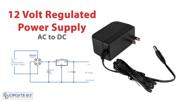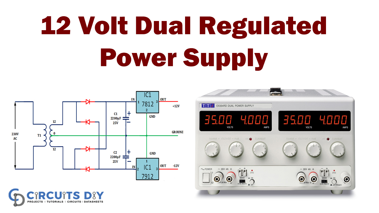
In this tutorial, we are demonstrating a circuit of a 12 Volt dual power supply regulated which is easy to make and requires a few low-cost components, and primarily uses two ICs LM7812 and LM7912 which are voltage regulator ICs and use for voltage conversion. This is a schematic of a controlled dual power supply that gives +12 V and -12 V from the AC mains.
This power supply is an extremely basic apparatus on the workbench of an electronic specialist.

Hardware Component
The following components are required to make a 12V Dual Power Supply Circuit
LM7812 Pinout
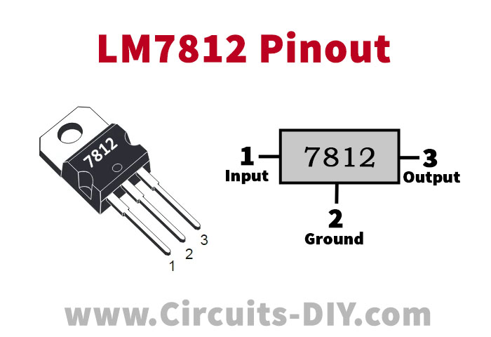
For a detailed description of pinout, dimension features, and specifications download the datasheet of LM7812
LM7912 Pinout
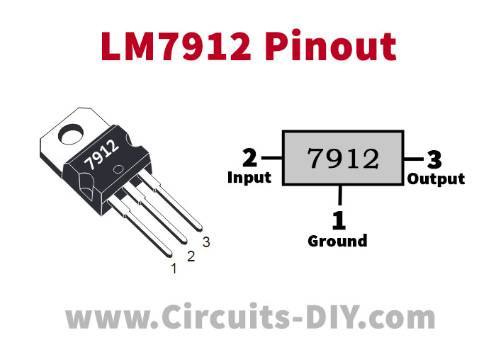
For a detailed description of pinout, dimension features, and specifications download the datasheet of LM7912
12V Dual Power Supply Circuit

Working Explanation
The circuit diagram given beneath is a regulated 12 V dual power supply circuit utilizing two voltage regulator ICs LM7812 and LM7912. Both the ICs are from the arrangement of LM78xx and LM79xx voltage controllers accessible in the TO-92 Transistor bundle. These ICs are worked to perform step-down DC to DC converter errands in electronic circuits and are generally utilized in power supplies and battery charger circuits.
The yield of both the ICs given in the underneath circuit are 12-volts however LM7812 is a “positive voltage controller” and LM7912 is a “negative voltage controller” IC. The transformer can be a 230 volt AC or 110 V AC to 15 V 1A. Utilize appropriate heatsinks with both ICs. The yield current of this power supply circuit is 1A.
Applications and Uses
This 12 V dual power supply can be utilized with the circuit which has an operational amplifier that requires double power sources.