You should always make sure to use an appropriate current limit when powering sensitive components. A regulated power supply converts unregulated AC to a constant DC. It is used to ensure that the output remains constant even if the input changes. A regulated power supply will usually have a knob to select a current limit and a knob to select a voltage. When a load is placed across the outputs of the power supply, the supply will attempt to maintain the selected open circuit voltage across the load. The current will continue to rise to maintain the selected voltage until the selected current limit is reached. At this point, the voltage across the load will be equal to the selected current multiplied by the load impedance. Here we design a simple 12V regulated power supply with easily available components.
Hardware Required
| S.No | Components | Value | Qty |
|---|---|---|---|
| 1 | Diode | 1N4001 | 4 |
| 2 | Capacitor | 100uF,0.1uF | 1,1 |
| 3 | IC | 7812 | 1 |
| 4 | Connecting Wires | – | – |
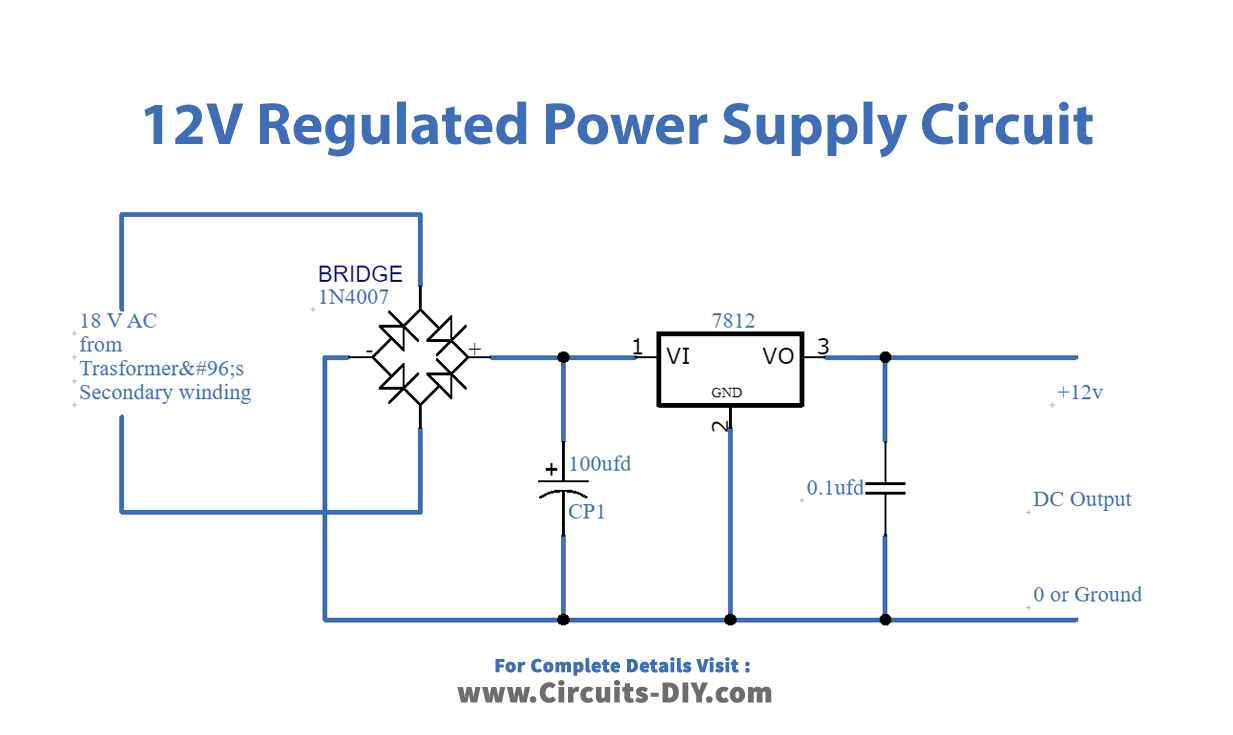
Circuit Diagram
Working Explanation
First, in this circuit, the bridge rectifier converts AC voltage into 12V DC. Here 100uF capacitor is used as a simple filter to remove large AC ripples from rectified DC, this DC output then comes in IC7812 for regulation. Further, the capacitor 0.1uF capacitor removes small-size AC ripples from regulated DC output.
Applications
In many electronic projects output actuators or output device needs 12 volt regulated power supply like LCD, Graphic LCD, and DC geared motors.