Introduction
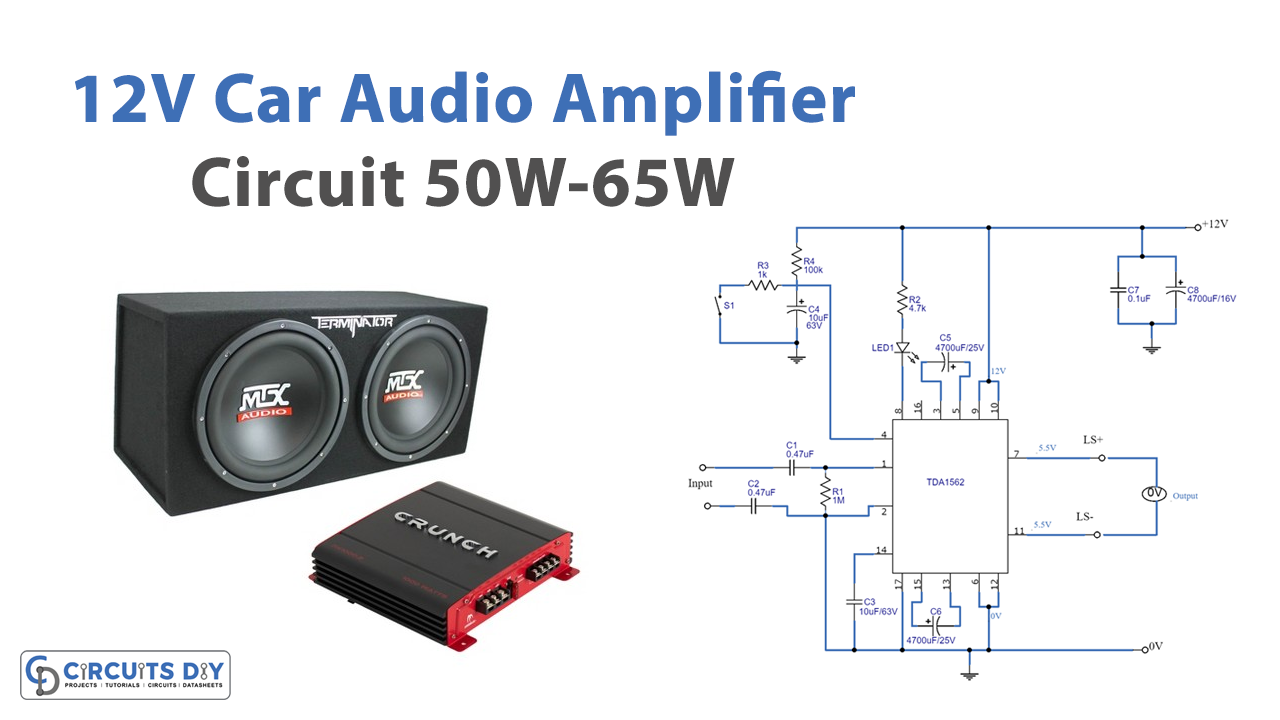
We frequently create audio amplifiers that amplify the audio signals for the electronics industry. The car sector is one of the best places to use audio amplifiers. For example, the audio amplifier is used to amplify the audio signal in vehicles such as autos. So, in this Tutorial, we are going to make a “12V Car Audio amplifier circuit 50W-65W”.
The TDA1562Q integrated radio amplifier is used in the circuit. The IC is reasonable and reasonably priced. Use a high-quality board while building the circuit, please. As the IC emits some heat, you may also utilize heat sinks.
Hardware Required
| S.no | Component | Value | Qty |
|---|---|---|---|
| 1. | IC | TDA1562Q | 1 |
| 2. | Resistor | 1K, 4.7K, 100K, 1M | 1, 1, 1, 1 |
| 3. | Ceramic Capacitor | 0.47uF, 0.1uF | 2, 1 |
| 4. | Electrolytic Capacitor | 10uF, 4700uF | 1, 3 |
| 5. | LED& Switch | – | 1,1 |
Circuit Diagram

Working Explanation
The input signal is sent to capacitors C1 and C2, which are used to couple the sound signal. Audio signals are delivered to pins 1 and 2 of IC1 to amplify the output to pins 7 and 11. Pi n 7 writes that LS + refers to offering the speaker’s positive. Pin 11 indicates that the LS means to connect to the speaker’s negative. It should be noted that the speaker’s terminal will be wired to the system’s ground. We already know that the circuit is linked to the bridge amplifiers. Therefore, if a speaker wire is connected incorrectly or to the ground. The detecting system will make an error right away. When the voltage at pin 8 approaches the negative voltage, current flows from the positive voltage through R2 and causes LED 1 to illuminate to alert the user to the issue.
The output of the lift level voltage circuit is wired to pins 3, 5, 13, and 15, to function as a boost current source and to increase voltage, and will be linked to the electrolytic capacitors C5, and C6, respectively.
Switch S1, R3, R4, and C4 are located at pin 4 of IC1, which is used to toggle between Stand-by and Mute modes. Assume that switching on S1 will now prepare itself before waiting for a simple voice to indicate that it is turned on and ready to function, but must wait first. Wait until the capacitor C4 has had time to charge through R4—this takes around one second. The letter “T” stands for the time delay, which is formulated as
T = R4xC4
Application Uses
- Suitable for Vehicle audio systems.