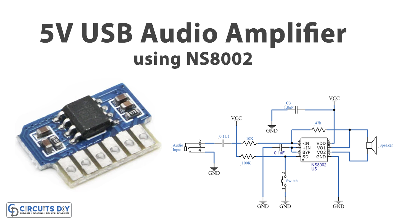
In this tutorial, we are going to make a “5V USB Audio Amplifier Circuit Diagram”. Audio amplifiers which are designed to work with a 5 V supply from a USB socket such as from a computer USB are called USB amplifiers. We should design a power portable audio amplifier, which consists of minimum component utilization and low power consumption. Here we construct a 5V USB audio amplifier circuit with NS8002 that will give a continuous 3 watts output. Here NS8002 is a bridged audio power amplifier, when you use 5V working voltage, the maximum drive power through it is 3W.
It has some important built-in features such as eliminating turn on/off transition noise, having unity gain that can be configured by an external gain setting resistor, and having a low power consumption shutdown mode which makes it useful for battery-powered devices. As you will see in the circuit, it doesn’t have any output coupling capacitor or bootstrap capacitors hence the size of the amplifier shrinks into a compact size. Which makes this circuit ideal for handheld applications.
Hardware Component
Audio Amplifier Circuit
| S.no | Component | Value | Qty |
|---|---|---|---|
| 1. | IC | NS8002 | 1 |
| 2. | Resistor | 10KΩ, 100KΩ, 47KΩ | 1, 1, 1 |
| 3. | Ceramic Capacitor | 0.1uF, 1uF | 2, 1 |
| 4. | Switch | – | 1 |
| 5. | Speaker | – | 1 |
NS8002 Pinout
For a detailed description of pinout, dimension features, and specifications download the datasheet of NS8002
Audio Amplifier Circuit
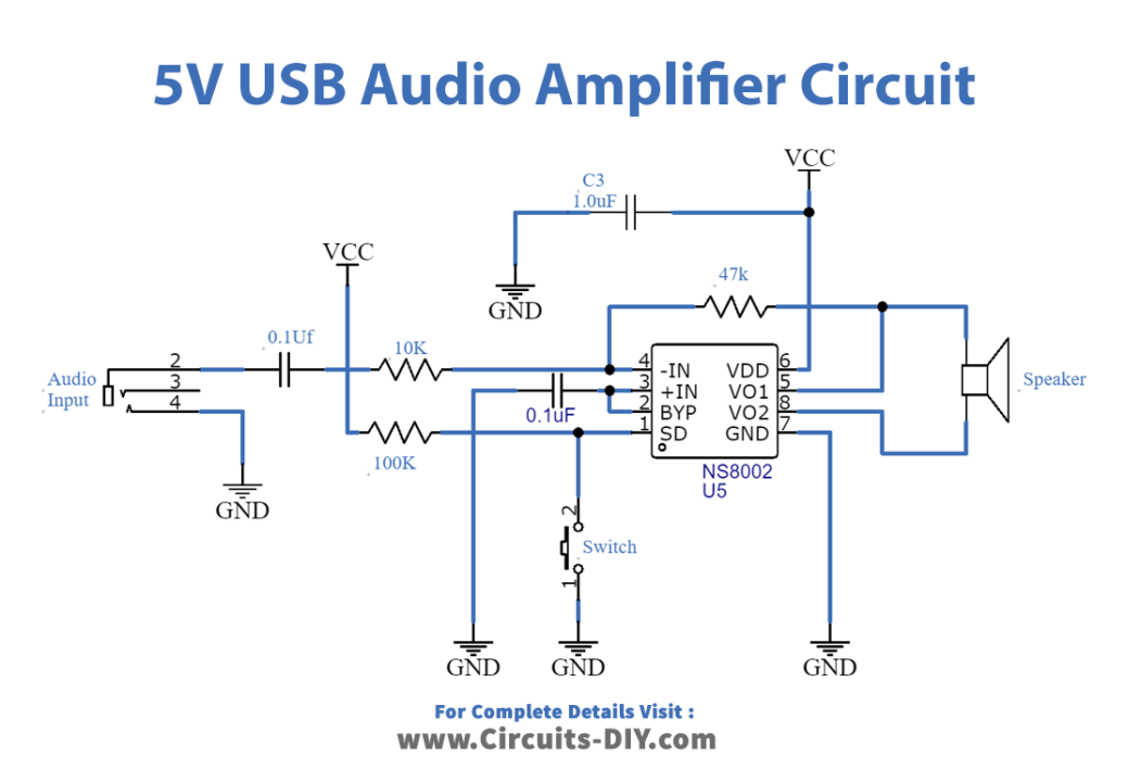
Working Explanation
This Amplifier IC NS8002 can operate in a wide range of voltages between 4.0V to 6.0V and it is most suitable for USB-powered applications (is particularly suitable for large-volume, low-weight portable systems). Due to its internal elements, this circuit requires few external resistors and capacitors only. It can enter hibernation mode by controlling, reducing power consumption and it has an automatic overheat shutdown protection mechanism, when a high level is applied to the SD pin (pin 1) this amplifier enters into shutdown mode, there is a switch connected between pin 1 and ground it represents low level if the switch gets open then the high level is applied.
It has a (BYP) Bypass capacitor pin (Pin 2) which provides the common-mode voltage. Pin 3 is +IN positive input of the first amplifier and receives the common-mode voltage through the C2 capacitor. Pin 4 is -IN Negative input of the first amplifier, receives the audio input signal through coupling capacitor C1 and R1 Resistor. Pin 5 is Vo1 it gives negative output for the loudspeaker. Pin 6 is Vcc and takes analog Vcc input supply (+5V), pin 7 is GND and takes ground connection for circuitry. Pin 8 is Vo2 it gives positive output for a loudspeaker. Resistor R3 is employed as a feedback resistor between input and output. By configuring the external resistors voltage gain of the amplifier can be adjusted to facilitate the application. When we powered the circuit with DC supply voltage (5V), it gives the best response if we use the 4-ohm loudspeaker.
Applications
Can be used on PC, laptops, and tablets.