
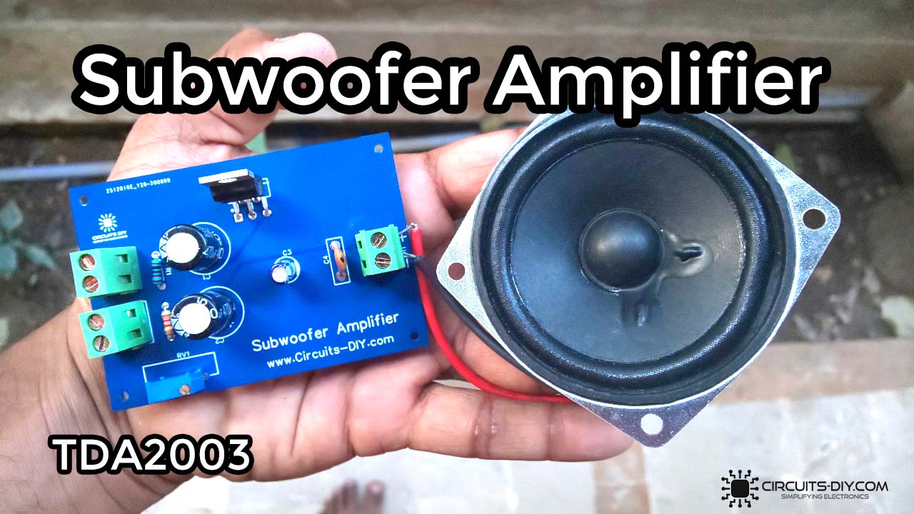
A Subwoofer Amplifier can be considered a loudspeaker that generates low-frequency audio signals. They’re specially configured electronic circuits that are used to enhance the signal strength & bass quality of any input audio signal. Subwoofer amplifiers find their use mainly in the entertainment industry where audio quality is of utmost importance in procedures such as live music production & recording. So in this tutorial, we will look into a step-by-step process on How to make a Subwoofer Amplifier circuit using TDA2003 audio amplifier IC.
The heart of this circuit is a TDA2003 10W audio amplifier IC. It is a general-purpose audio amplifier IC that is useful in stereo or mono audio design circuits. The amplifier can output up to 3.5A current to drive speakers and can also handle high currents up to 5A for a short duration without any damage.

PCBWay commits to meeting the needs of its customers from different industries in terms of quality, delivery, cost-effectiveness, and any other demanding requests. As one of the most experienced PCB manufacturers in China. They pride themselves to be your best business partners as well as good friends in every aspect of your PCB needs.
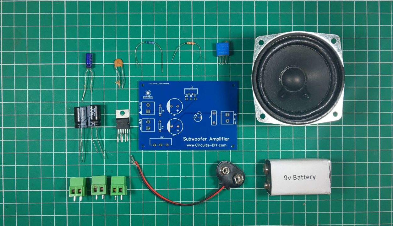
Hardware Components
The following components are required to make Subwoofer Amplifier Circuit
| S.no | Component | Value | Qty |
|---|---|---|---|
| 1. | Audio Amplifier IC | TDA2003 | 1 |
| 2. | Loud Speaker | 16 Ohm | 1 |
| 3. | Audio Jack (Male) | 3.5mm | 1 |
| 4. | Subwoofer Amplifier PCB | – | 1 |
| 5. | Potentiometer | 100K | 1 |
| 6. | Electrolytic Capacitors | 470uF, 2.2uF | 2, 1 |
| 7. | Ceramic capacitor | 250pF | 1 |
| 8. | Soldering Iron | 45W – 65W | 1 |
| 9. | Soldering Wire With Flux | – | 1 |
| 10. | Resistor | 2.2 Ohm, 220 Ohm | 2 |
| 11. | DC Battery | 12V | 1 |
| 12. | Battery Clip | – | 1 |
| 13. | Smartphone/PC | – | 1 |
TDA2003 Pinout
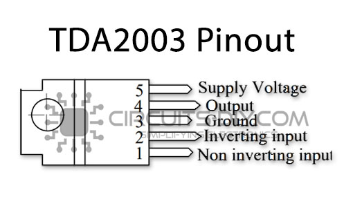
For a detailed description of pinout, dimension features, and specifications download the datasheet of TDA2003
Subwoofer Amplifier Circuit
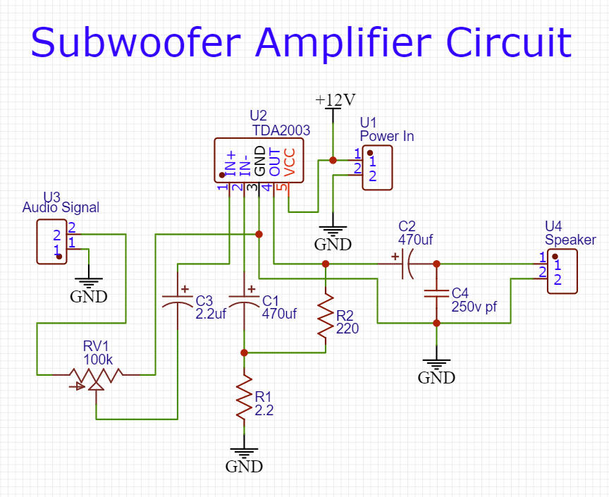
Working Explanation
A subwoofer amplifier works on the following principle. Audio input is taken from a device such as a smartphone. Here a 2.2uF coupling capacitor (C3) is used to block any DC signal, allowing only the AC component of the signal to move on towards the input pin IN+ pin of the TDA2003 amplifier IC.
The output from the audio amplifier IC then goes through a filtering capacitor (C2) to filter out any residual noise from the IC output signal before allowing it to move on towards the output. The output audio signal can be taken on any loudspeaker of appropriate resistance. connect a 1.8pF 250V film capacitor in case the speaker output is noisy.
Application
- It is generally used in devices such as home theater systems so that the speakers can produce noise-free high bass music of high quality.
Related posts:
 Do's & Dont's of PCB Designing - Tips & Best Practices
 37 Volt Variable Power Supply with LM317 IC
 How To Make a Simple Audio Amplifier Using a 2SC2625 Transistor
 Two Transistor Audio Amplifier Circuit
 Hot and Cold Water Cooler Using A Peltier Thermoelectric Cooling Module
 Simple Microphone to Speaker Amplifier Circuit


