Introduction
In this Tutorial, we are going to make a “60 Watt Stereo Amplifier Circuit using LM3876”. As we know that amplifier is an electronic device, used mostly in sound reproduction to increase the loudness of electrical signals.
In the making of this 60W amplifier, we are using LM3876 IC. So, before we begin, we must first understand the IC LM3876. The integrated circuit belongs to the national semiconductor. This IC is also used in self-powered speakers, tiny stereos, and other devices due to its strong performance. It also has a wide supply voltage range. The IC operates between 12 and 49 volts DC. It also boasts a higher signal-to-noise ratio. However, because it distributes heat, it requires a heat sink.
Hardware Required
| S.no | Component | Value | Qty |
|---|---|---|---|
| 1. | IC | LM3876 | 1 |
| 2. | Resistor | 10 Ohm, 22K, 1K, 18K, 2.7 Ohm, 27K | 1, 1, 2, 1, 1, 1 |
| 3. | Capacitor | 220pF, 22uF, 220uF, 0.1uF | 1, 2, 2, 3 |
| 4. | Switch & Fuse | 2A | 1, 2 |
| 5. | Speaker | – | 1 |
| 6. | Inductor | – | 1 |
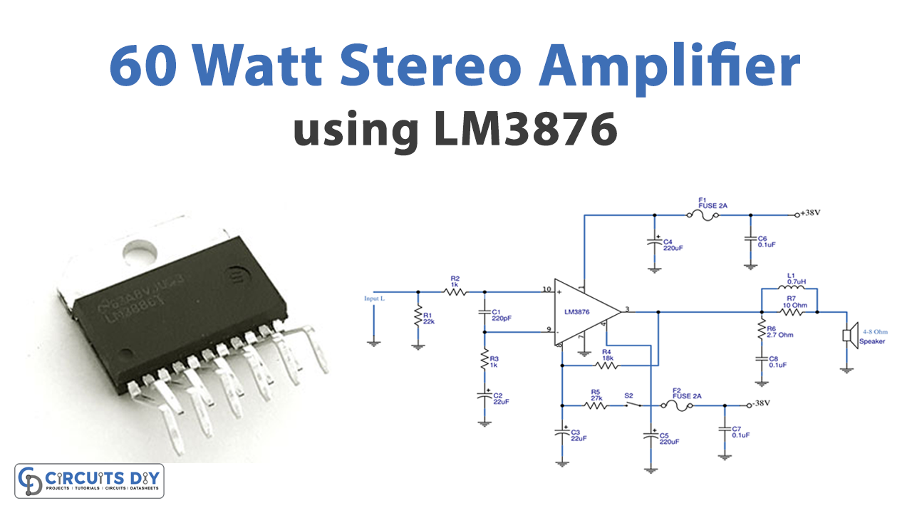
Circuit Diagram

Working Explanation
Power Supply Circuit for 60W Stereo Amplifier
First, we need to make a power supply circuit that provides 38V which will become the input for the stereo amplifier.

The power supply includes a C9-capacitor that connects the switch S1 to an output speaker that makes no loud banging noises. the opening noise A transformer designated T1, will then reduce the voltage to 27 volts AC and 4 amps. Then, via BD1, the voltage shifts to DC at roughly +-38 volts. Capacitors C10 and C11 reduce the noise.
And then, unless it is also designed for the audio tone control circuit, the voltage +-38V will be reduced to lower voltage by R8-R11 to protect voltage across IC2 and IC3 from being too high, and the voltage will be reduced lower to +15 volts through the regulated circuit, by IC2-LM7815 will be the positive voltage of 15 Volts and IC3 is the negative voltage of 15 Volts.
60-Watt Amplifier Circuit in Stereo
The sound signal will transit through RC networks that include R2 and C1 to protect radio signal interference and attenuate the RF signal before it enters pin 10 of IC1, which is attached as a non-inverter tig amplifier with a gain rate of 19 times. This gain is derived from feedback at the input via R4 and R3. Calculated using the formula (1 + R4/R3). When C2 is connected to R3, the lower frequency is reduced to -3dB at 7 Hz.
The boosted audio signal will exit IC1 via pin 3. However, before this signal reaches the speaker, it must pass via a Zobel Network circuit composed of R6 and C8. To resolve the issue that is driving the load capacity and maintaining high-frequency stability, we are using an RL network with a 0.7 uH coil.
This S2 is a switch that controls the operation of a circuit inside IC1. This circuit type has special characteristics that are typically included with amplifier ICs. If S2 is closed in this circuit, the regular sound is output through the speaker. However, when S2 is open because the circuit is not connected, the sound produced by the speaker is roughly 110 dB faint. The capacitor-C3 connected to pin 8 of IC1 will induce a minor rise in sound level to normal. S2 then returns to the closed circuit. To keep spikes from coming out of the speaker.
Application Uses
- Hi-fi devices
- Home audio systems
- Robots and toys
- Radio wave transmitter