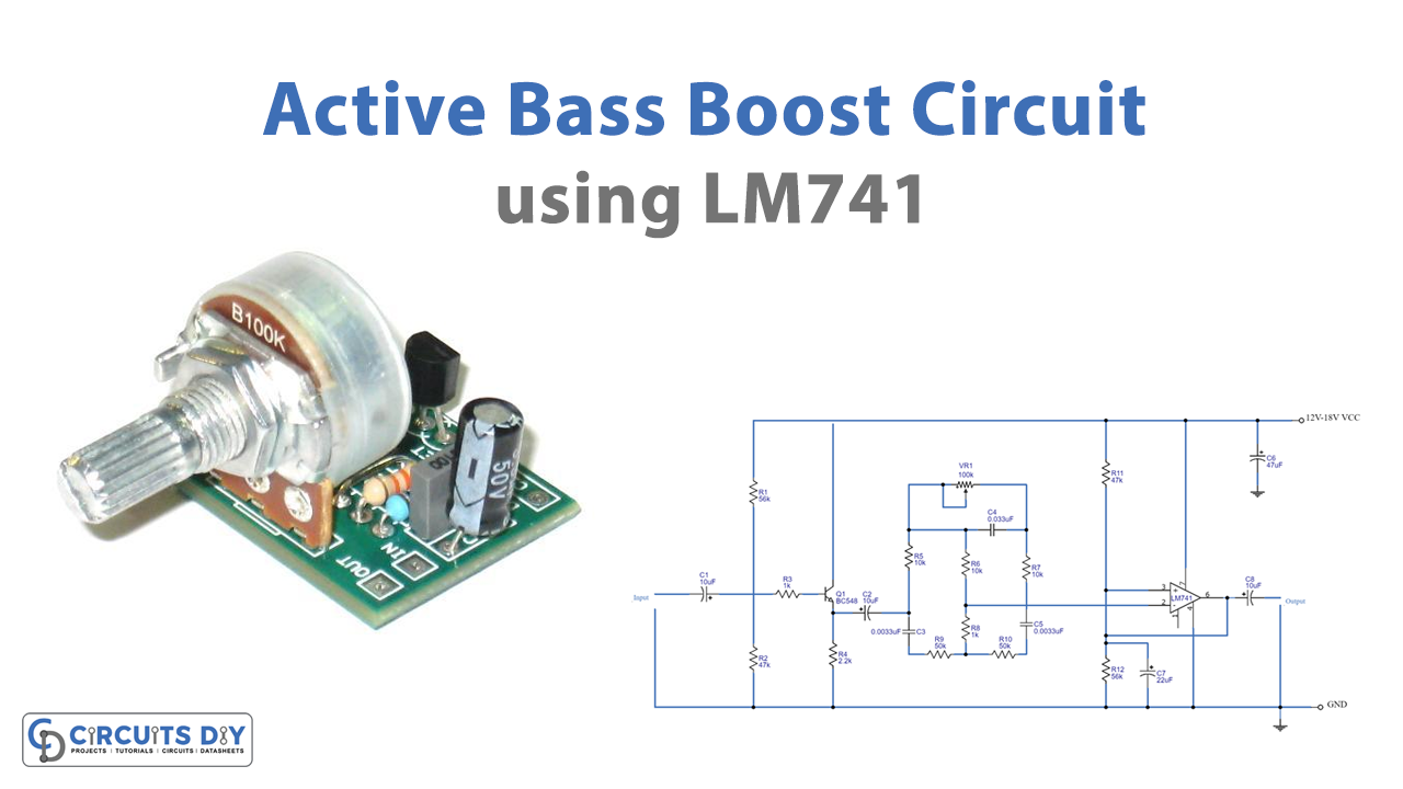
In this Tutorial, we are going to make an “Active Bass Boost circuit using IC-741”. A bass booster electronic circuit collaborates with an amplifier circuit to enhance the output response. Basic consumer gadgets like speakers and headsets frequently have them.
Any audio system’s audio quality improves when the bass is turned up. Adding several components to an electronic circuit is a frequent way to do this. The obvious requirement is that it has an audio input so you can connect it to your speakers. With this method, you may also anticipate becoming more immersed in the overall listening experience. Additionally, the bass boost circuit functions as a volume, gain, and bass control circuit as well.
In this bass boost circuit, we are using IC 741. The main purpose of this 741 op-amp IC is to boost AC and DC signals as well as perform mathematical computations.
Specifications of 741 Opamp IC
- Power Supply: Requires a Minimum voltage of 5V and can withstand up to 18V
- Input Impedance: About 2 MΩ
- Output impedance: About 75 Ω
- Voltage Gain: 200,000 for low frequencies (200 V / mV)
- Maximum Output Current: 20 mA
- Recommended Output Load: Greater than 2 KΩ
- Input Offset: Ranges between 2 mV and 6 mV
- Slew Rate: 0.5V/µS (It is the rate at which an Op-Amp can detect voltage changes)
Hardware Required
| S.no | Component | Value | Qty |
|---|---|---|---|
| 1. | IC | LM741 | 1 |
| 2. | Resistor | 56K, 47K, 1K, 10K, 50K, 2.2K | 2, 2, 1, 4, 2, 1 |
| 3. | Capacitor | 10uF, 0.0033uF, 47uF, 22uF | 3, 3, 1, 1 |
| 4. | Transistor | BC548 | 1 |
| 5. | Variable Resistor | 100K | 1 |
Circuit Diagram
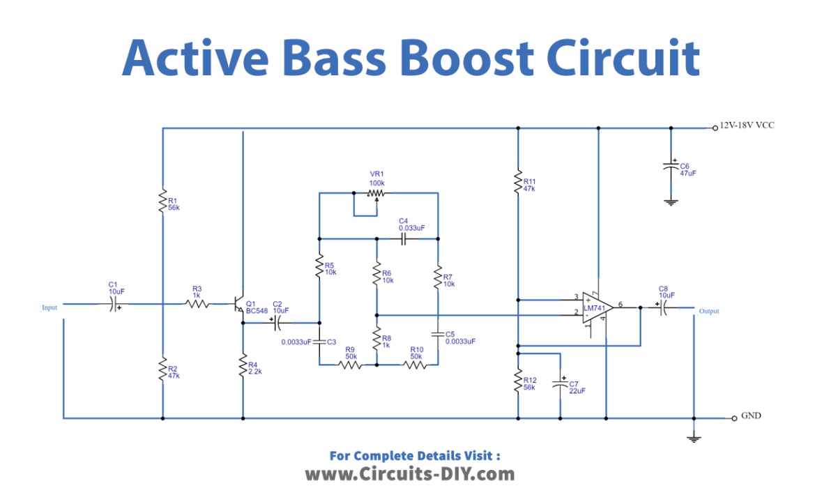
Working Explanation
While supplying the power to this Active Bass Boost circuit using IC 741, we input an audio signal through a coupling capacitor C1, is. The signal then goes via R3 to the base of Q1. Thus R1 and R2 work together as a voltage divider to control Q1’s bias current. As part of a typical preamplifier circuit, Q1, C1, R1, R2, R3, R4, and C2 are linked to one another. They will initially enhance a signal by one level. The signal is then coupled to the low pass filter section by a higher single exiting Q1’s emitter through C2. An initial signal is then sent by C3, C5, R8, R9, and R10. They will drive a lot of people away. Additionally, a second signal entered R5, R6, R7, and C4.
By altering potentiometer VR1, we may greatly alter the low-frequency level or the bass sound. At pin 2 of IC1, 741 op-amps, both signals are then combined. One of the most well-liked ICs. And IC1 increases its level upon output from pin 6. Additionally, certain signals from pin 6 were again sent into the frequency filter. to regulate the gains on the high-stability circuit’s frequency ratio. before directing it to the subsequent external preamplifier
Application Uses
- Earphones
- Speakers
- Gaming headsets to enhance the listening experience.