Introduction
Have you ever wondered how to build a circuit alerting you when the temperature in a room or area exceeds a specific limit? Look no further! This article will dive into the exciting world of electronics and create a temperature alarm circuit that is both easy to build and extremely useful.
This circuit is perfect for beginners who are just starting to explore the world of electronics, and it’s a great way to learn about the different components and how they work together to create a functioning circuit. So grab your electronic components and build our own temperature alarm circuit!
Hardware Required
You will require the following hardware for Temperature Alarm Circuit.
| S.no | Component | Value | Qty |
|---|---|---|---|
| 1. | IC | NE555 Timer, 7812, LM741 | 1, 1, 1 |
| 2. | Capacitor | 470, 330, 10n, 100, 2N2, 10uF | 1, 1, 1, 1, 1, 2 |
| 3. | Resistor | 33, 1K, 56K, 10K, 150K, 560, 10M | 1, 1, 2, 2, 1, 2, 1 |
| 4. | NTC Resistor | 10K, 2K5 | 1, 1 |
| 5. | Bridge Rectifier | 1N4007 | 1 |
| 6. | Transistor | BC557 | 1 |
| 7. | Transformer | 15V / 150mA | 1 |
| 8. | Switch | – | 1 |
| 9. | Buzzer | – | 1 |
Circuit Diagram
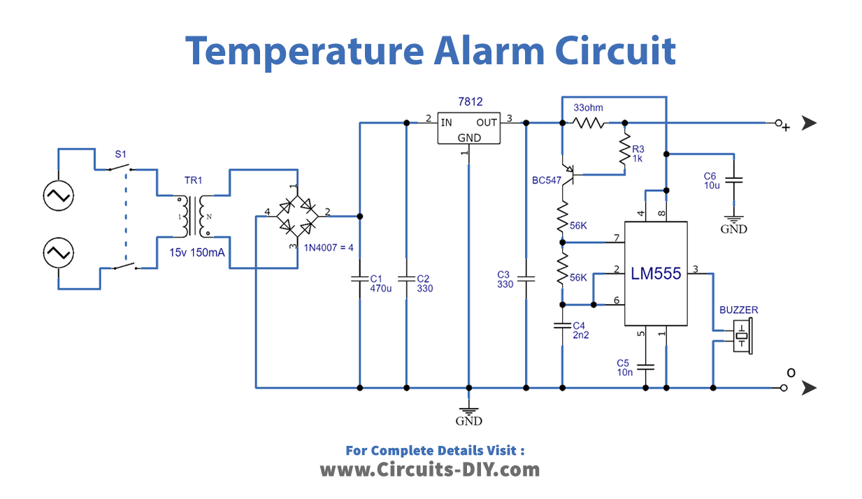
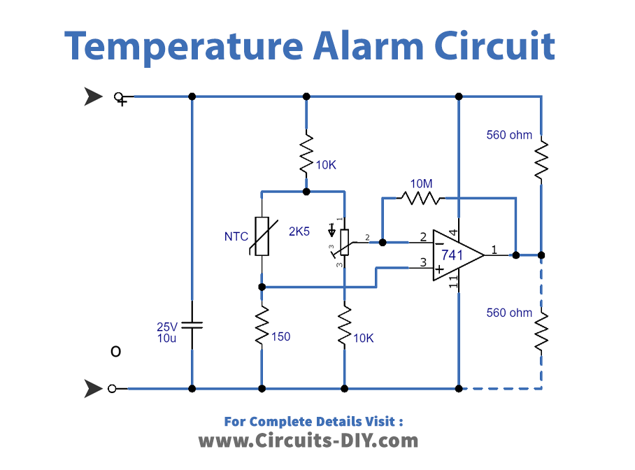
Working Explanation
This temperature alarm uses a resistor (R10) to determine the temperature setting at which the alarm is triggered. If R10 is connected between the positive supply line and the output of IC3, the alarm will get triggered when the temperature goes above what P1 is set to. This happens because the temperature increases and the resistance of the NTC resistor (R9) decreases, causing the inverting input of IC3 to be higher than the non-inverting input, which in turn causes the output of the opamp to go low.
On the other hand, if R10 is connected between IC2’s output and ground, the alarm will be triggered when the temperature drops below the setting of P1. This is because as the temperature falls, the resistance of R9 increases, causing the inverting input of IC3 to be lower than the non-inverting input, which in turn causes the output of the opamp to go high.
The sensitivity of the circuit, or the temperature at which it operates, can be adjusted using the preset potentiometer P1. The circuit also includes a transistor (T1) and an oscillator (IC2) that produces a 4kHz tone to drive a piezo-electric buzzer (Bz) when the alarm is triggered. The circuit can handle up to four detector circuits.
Applications
- Simple Fire alarm
- The temperature control system
- Temperature regulator for central heating installations.
Final Words
In conclusion, a temperature alarm circuit is helpful to alert the user when a certain temperature threshold is reached. It can be used in various applications, such as monitoring the temperature of a room, etc. We hope you found this article informative and helpful. If you have any queries or comments, please feel free to leave them below.