
Overview
In the world of modern technology, where digital clocks and smartphones have become ubiquitous, there’s something charmingly nostalgic about the simplicity and elegance of an analog clock. Creating your own analog clock using the ESP32 microcontroller and an SSD1306 OLED display not only combines the best of both worlds – the classic aesthetics of analog timekeeping and the power of modern electronics but also makes for a fascinating DIY project
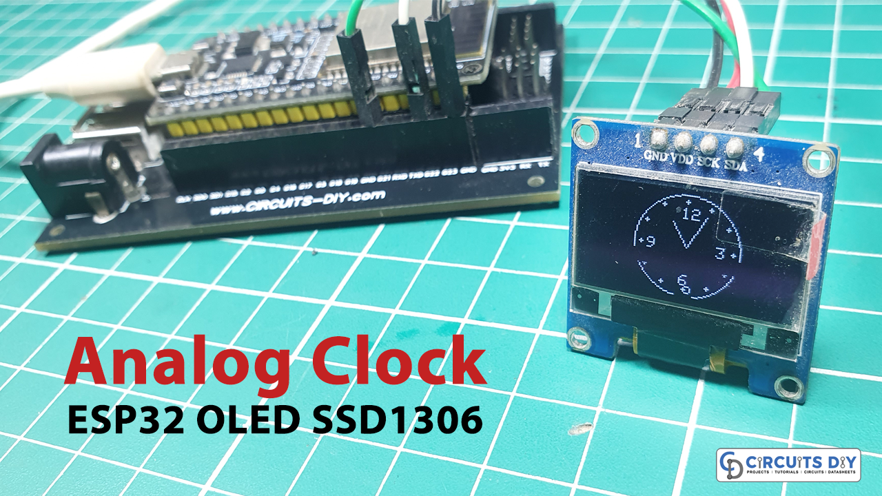
In this project, we’re gonna build an ESP32 Analog Clock with an NTP server’s help and display it on an OLED display.
NTP Server
NTP stands for Network Time Protocol. An NTP server is a specialized computer or device that provides highly accurate time information to other devices over a network, typically the Internet. These servers are synchronized with highly precise time sources, such as atomic clocks or GPS receivers, and they distribute this accurate time information to other devices, helping them maintain accurate timekeeping.
In the context of the ESP32 project mentioned earlier, the ESP32 uses NTP servers to synchronize its internal clock with the most accurate time available on the internet. This ensures that the analog clock displayed on the OLED screen is always precise and in sync with global time standards. NTP servers play a crucial role in various applications, including network synchronization, data logging, financial transactions, and many more where precise timing is essential.
This Project is sponsored by PCBWay. They have an open-source community, people can share their design projects with each other. Moreover, every time people place an order for your board, PCBWay will donate 10% of the cost of PCB to you, for your contribution to the Open Source Community.

Hardware Components
You’ll need the following hardware components to get started:

| Components | Value / Model | Qty |
|---|---|---|
| ESP32 | – | 1 |
| OLED Display | SSD1306 | 1 |
| Jumper Wires | – | 1 |
| DC Power for ESP32 |
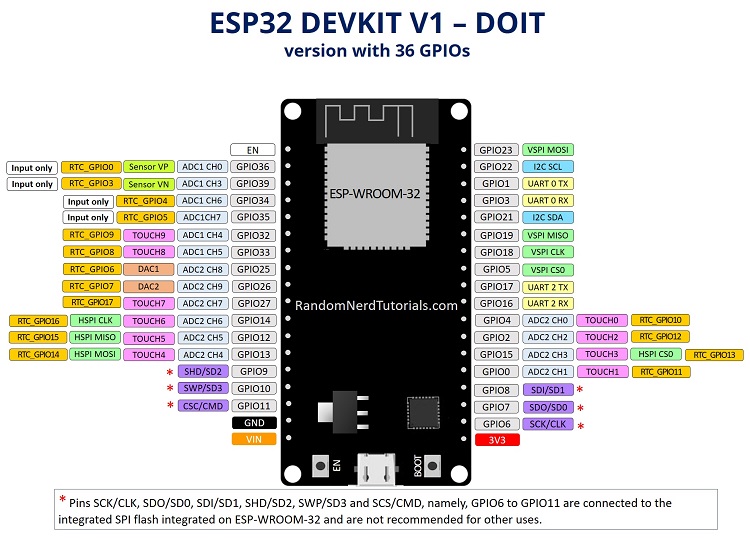
ESP32 Pinout
Steps-by-Step Guide
(1) Setting up Arduino IDE
Download Arduino IDE Software from its official site. Here is a step-by-step guide on “How to install Arduino IDE“.
(2) ESP32 in Arduino IDE
There’s an add-on that allows you to program the ESP32 using the Arduino IDE. Here is a step-by-step guide on “How to Install ESP32 on Arduino IDE“.
(3) Include Libraries
Before you start uploading a code, download and unzip the Wire.h, Adafruit_GFX.h, Adafruit_SSD1306.h, WiFi.h, time.h, sntp.h library at /Program Files(x86)/Arduino/Libraries (default). Here is a step-by-step guide on “How to Add Libraries in Arduino IDE“.
(4) Schematic
Make connections according to the circuit diagram given below.

Wiring / Connections
| ESP32 | SSD1306 OLED Display |
|---|---|
| 3V3 | VCC |
| GND | GND |
| GPIO 22 | SCL |
| GPIO 21 | SDA |
(5) Uploading Code
Now copy the following code and upload it to Arduino IDE Software.
/* Circuits DIY
 * For Complete Details Visit
 * https://www.circuits-diy.com/analog-clock-using-esp32-ssd1306-oled-display/
 */

#include <Wire.h>
#include <Adafruit_GFX.h>
#include <Adafruit_SSD1306.h>

#include <WiFi.h>
#include "time.h"
#include "sntp.h"

const char* ssid = "Circuits DIY";
const char* password = "20244064";

const char* ntpServer1 = "pool.ntp.org";
const char* ntpServer2 = "time.nist.gov";
const long gmtOffset_sec = 3600;
const int daylightOffset_sec = 3600;

int hrs=0;
int mins=0;
int secs=0;

Adafruit_SSD1306 display(128, 64, &Wire, -1);

const int NUM_POINTS = 60;
const int RADIUS = 28;

int pointsX[NUM_POINTS];
int pointsY[NUM_POINTS];

void setup() {
  Serial.begin(115200);
  // set notification call-back function
  sntp_set_time_sync_notification_cb(timeavailable);
  //sntp_servermode_dhcp(1);  // (optional)
  configTime(gmtOffset_sec, daylightOffset_sec, ntpServer1, ntpServer2);

  //connect to WiFi
  Serial.printf("Connecting to %s ", ssid);
  WiFi.begin(ssid, password);
  while (WiFi.status() != WL_CONNECTED) {
    delay(500);
    Serial.print(".");
  }
  Serial.println(" CONNECTED");

  /***************************************************/

  display.begin(SSD1306_SWITCHCAPVCC, 0x3C);  //initialize the display with I2C address 0x3C
  display.clearDisplay();                     //clear the display buffer
  display.display();                          //update the display

  for (int i = 0; i < NUM_POINTS; i++) {
    pointsX[i] = 64 + RADIUS * cos(i * 6.28 / NUM_POINTS);
    pointsY[i] = 32 + RADIUS * sin(i * 6.28 / NUM_POINTS);
  }
}

void loop() {
  setLocalTime();
  //calculate the angle for each hand
  float secAngle = map(secs, 0, 60, 0, 360);
  float minAngle = map(mins, 0, 60, 0, 360);
  float hrAngle = map(hrs, 1, 12, 30, 360);

  //calculate the positions of the hands
  int hrX = 64 + (RADIUS - 11) * cos((hrAngle - 90) * PI / 180);
  int hrY = 32 + (RADIUS - 11) * sin((hrAngle - 90) * PI / 180);
  int minX = 64 + (RADIUS - 6) * cos((minAngle - 90) * PI / 180);
  int minY = 32 + (RADIUS - 6) * sin((minAngle - 90) * PI / 180);
  int secX = 64 + (RADIUS)*cos((secAngle - 90) * PI / 180);
  int secY = 32 + (RADIUS)*sin((secAngle - 90) * PI / 180);

  display.clearDisplay();  //clear the display buffer

  //draw the clock face
  display.drawCircle(64, 32, 32, WHITE);  //Draw a Center Point
  //Draw 12 Clock points
  for (int i = 0; i < NUM_POINTS; i += 5) {
    display.fillCircle(pointsX[i], pointsY[i], 1, WHITE);
  }

  //Display Numbers 12-3-6-9
  display.setTextSize(1);
  display.setTextColor(SSD1306_WHITE);

  for (int i = 12; i > 1; i -= 3) {
    float angle = map(i, 1, 12, 30, 360);
    int xPos = 64 + (RADIUS - 7) * cos((angle - 90) * PI / 180) - 3;
    int yPos = 32 + (RADIUS - 7) * sin((angle - 90) * PI / 180) - 3;
    display.setCursor(xPos, yPos);
    display.print(i);
  }

  //draw the hour hand
  display.drawLine(64, 32, hrX, hrY, WHITE);

  //draw the minute hand
  display.drawLine(64, 32, minX, minY, WHITE);

  //draw the Second hand
  //display.drawLine(64, 32, secX, secY, WHITE);
  display.drawCircle(secX, secY, 2, WHITE);

  //update the display
  display.display();
  delay(1000);
}


void setLocalTime() {
  struct tm timeinfo;
  if (!getLocalTime(&timeinfo)) {
    Serial.println("No time available (yet)");
    return;
  }
  Serial.println(&timeinfo, "%A, %B %d %Y %H:%M:%S");

  hrs = timeinfo.tm_hour;
  mins = timeinfo.tm_min;
  secs = timeinfo.tm_sec;

}

// Callback function (get's called when time adjusts via NTP)
void timeavailable(struct timeval* t) {
  Serial.println("Got time adjustment from NTP!");
  setLocalTime();
}
How code works
#include <Wire.h>
#include <Adafruit_GFX.h>
#include <Adafruit_SSD1306.h>

#include <WiFi.h>
#include "time.h"
#include "sntp.h"
This section includes various libraries necessary for the project. These libraries provide functions and tools for working with I2C communication, OLED display, Wi-Fi connectivity, and time management.
const char* ssid = "Circuits DIY";
const char* password = "20244064";

const char* ntpServer1 = "pool.ntp.org";
const char* ntpServer2 = "time.nist.gov";
const long gmtOffset_sec = 3600;
const int daylightOffset_sec = 3600;
These variables store Wi-Fi credentials and NTP server information. They are used to connect to a Wi-Fi network and synchronize the device’s time with an NTP server.
int hrs=0;
int mins=0;
int secs=0;

Adafruit_SSD1306 display(128, 64, &Wire, -1);

const int NUM_POINTS = 60;
const int RADIUS = 28;

int pointsX[NUM_POINTS];
int pointsY[NUM_POINTS];
This section declares various global variables:
hrs,mins, andsecsstore the current time components.displayis an instance of theAdafruit_SSD1306class for controlling the OLED display.NUM_POINTSandRADIUSdefine parameters for drawing clock points and circles on the display.- Arrays
pointsXandpointsYstore coordinates for points on the clock face.
void setup() {
  // ...
}
This function runs once during the startup of the microcontroller. It performs various initialization tasks, including setting up serial communication, configuring time synchronization, connecting to Wi-Fi, initializing the OLED display, and calculating clock point coordinates.
void loop() {
  // ...
}
The loop() function is the main program loop that runs continuously. It reads and sets the local time, calculates angles and positions for clock hands, draws the clock face and hands on the OLED display, and updates the display every second.
void setLocalTime() {
  // ...
}
This function retrieves the local time from the ESP32’s real-time clock (RTC) and updates the global time variables (hrs, mins, and secs) accordingly.
void timeavailable(struct timeval* t) {
  // ...
}
This is a callback function that gets called when the time is adjusted via NTP synchronization. It calls the setLocalTime() function to update the time variables.
In summary, this code sets up an ESP32-based analog clock that synchronizes its time with an NTP server and displays the time on an OLED screen. It’s organized into sections for library inclusion, setup, the main program loop, and functions to manage time and handle callbacks.
Applications
- Home Decor: Create a stylish and functional analog clock to adorn your home or workspace
- Prototyping: Explore the project as a starting point for prototyping more advanced IoT (Internet of Things) devices that require time synchronization.
- DIY Gifts: Craft personalized analog clocks as unique and thoughtful gifts for friends and family, adding a personal touch by customizing the clock face design.
Conclusion
The Analog Clock project using ESP32 and SSD1306 OLED Display is like combining the old-fashioned beauty of traditional clocks with the power of modern technology. It lets you create your own clock that shows the time very accurately. You can use it as a cool decoration in your home, a fun learning experience, or even a starting point for more advanced projects
Related posts:
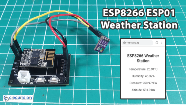 Simple ESP8266 Weather Station with BME280
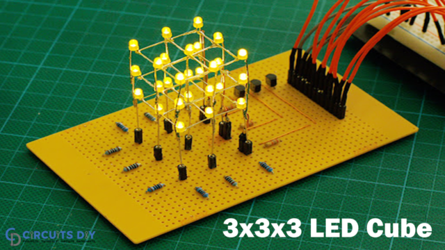 3x3x3 LED Cube using 555 Timer and CD4060 IC
 Voltage Level Indicator Using LM3914 Dot/Bar Display Driver IC
 Dual LED Flasher using Relay | Flip Flop LED Circuit
 Fridge Door Alarm Circuit - Electronics Projects
 How To Make An Electronic Fuse Circuit | DIY Project


