Introduction
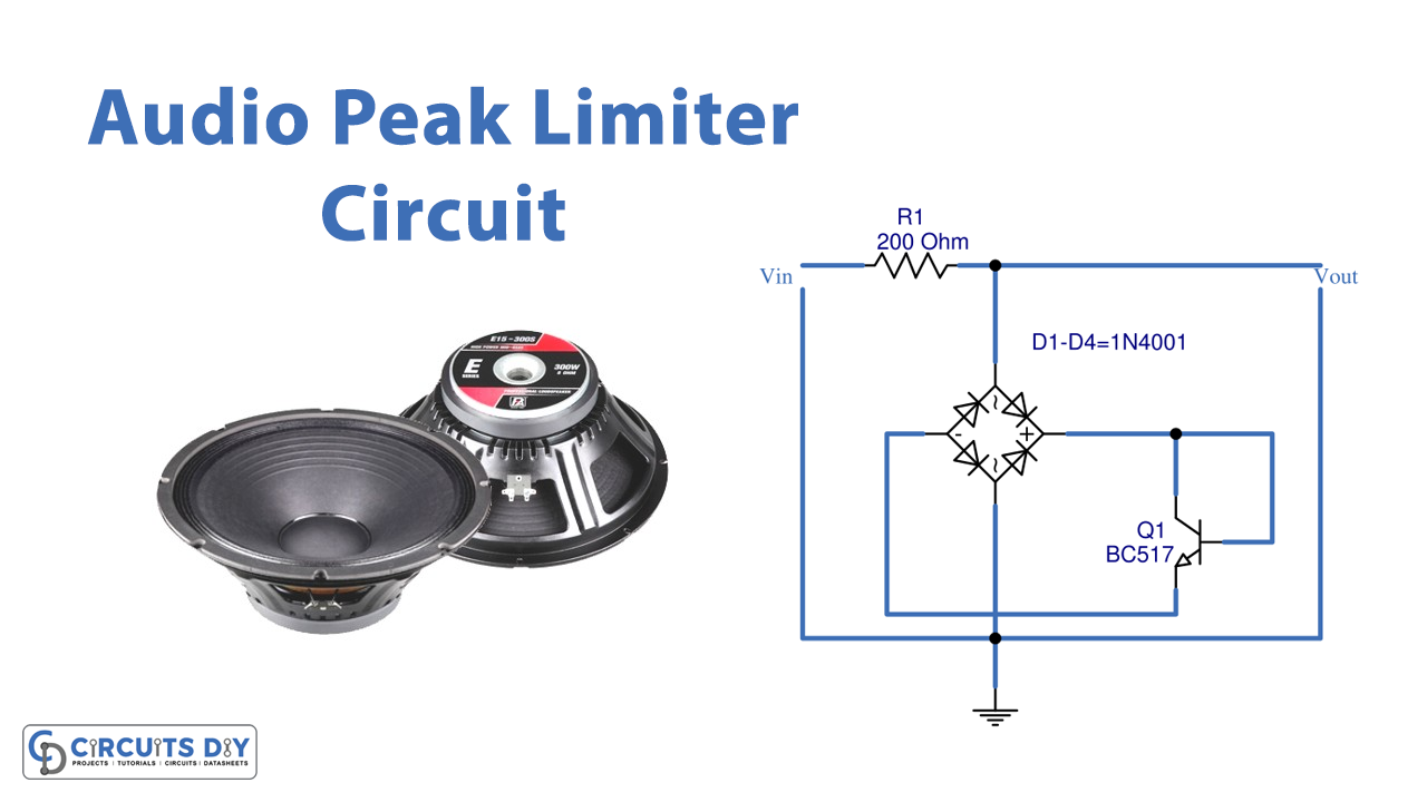
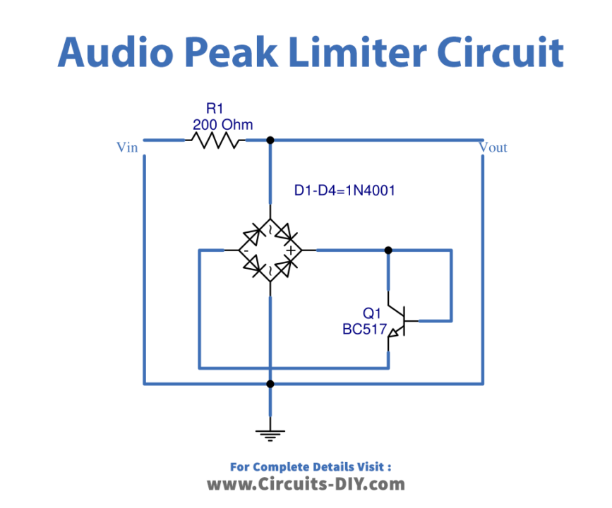
In this Tutorial, we are going to make an “Audio peak limiter circuit to improve input signal”. An effect is known as a “peak limiter” and “pushes down” on peaks to lower their level. It is a type of dynamic range compression effect. Limiters don’t affect the audio around them very much, compared to other compressor effects, except for a few milliseconds on either side of the peak. They may be creatively employed to strengthen drum sounds and are especially helpful for eliminating “transients” which are extremely brief loud noises that would otherwise restrict the audio from being amplified without distortion.
Hardware Required
Circuit Diagram
Working Explanation
In this simple Audio peak limiter circuit, resistor R1 serves as a current limiter when an input voltage is present. The current then flows from diodes D1 to D4 in the form of bridge diodes. These circuits use a full-wave rectifier to change ACV into DCV. Reason? The Q1 prefers DCV since it is an NPN transistor. However, it won’t begin to operate until the input voltage exceeds 1V RMS. The current will flow through the transistor Q1. It appears that there is a short circuit between the collector and emitter. Therefore, the input signal cannot be sent from the output to the power amplifier’s input.
Application Uses
- To avoid broadcast transmitters becoming overmodulated.
- To avoid distortion brought on by too many audio recorders.
- To stop analog-to-digital converters from going into overdrive.
- To safeguard speakers that are loud in public address systems.