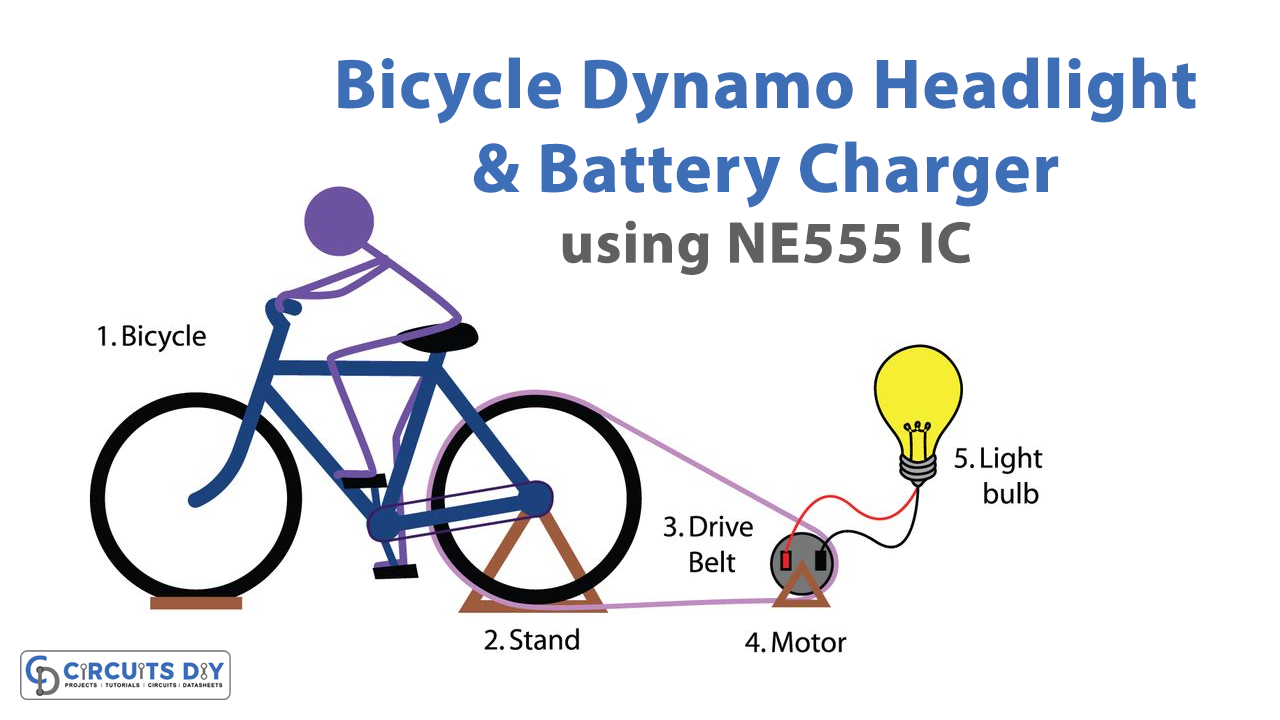
In this tutorial, we are making a project of an Automatic Bicycle Dynamo Headlight and Battery charger circuit. This circuit is completely automatic. It turns the LED off during the daytime and connects the dynamo with a charger circuit. In this way, the dynamo will charge the 6V 4.5AH battery while you are riding the bicycle. Now the battery will store a good amount of power and you can use this power for charging and powering any device.
Hardware Components
The following components are required to make the Automatic Dynamo Headlight Circuit
| S.no | Component | Value | Quantity |
|---|---|---|---|
| 1. | Bicycle dynamo | 6V/3W | 1 |
| 2. | Diode | 1N5822, 1N4148 | 1, 2 |
| 3. | Voltage Regulator IC | LM2904T-8.0 | 1 |
| 4. | Transistor | BD139, BD140, 2N3904 | 1, 1, 1 |
| 5. | Switch | – | 1 |
| 6. | Zener Diode | 3.3V | 1 |
| 7. | Phototransistor | PC817 | 1 |
| 8. | Resistor | 4.7KΩ, 8.2KΩ, 1KΩ, 10KΩ, 470KΩ, 50KRΩ | 1, 1, 2, 1, 1, 1 |
| 9. | Potentiometer | 100KΩ | 1 |
| 10. | Electrolytic Capacitor | 2200µF/25V, 22µF | 1, 1 |
| 11. | Relay | – | 1 |
| 12. | LED | – | 2 |
| 13. | Ceramic Capacitor | 10nF, 0.47µF | 1, 1 |
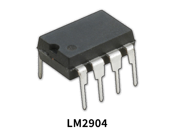
LM2904 Pinout
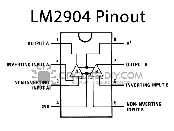
For a detailed description of pinout, dimension features, and specifications download the datasheet of LM2904
2N3904 Pinout
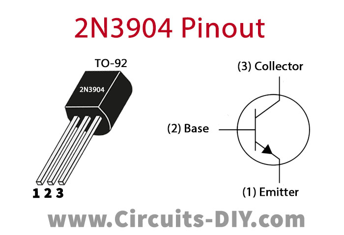
For a detailed description of pinout, dimension features, and specifications download the datasheet of 2N3904
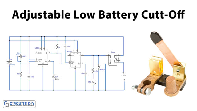
Automatic Dynamo Headlight Circuit
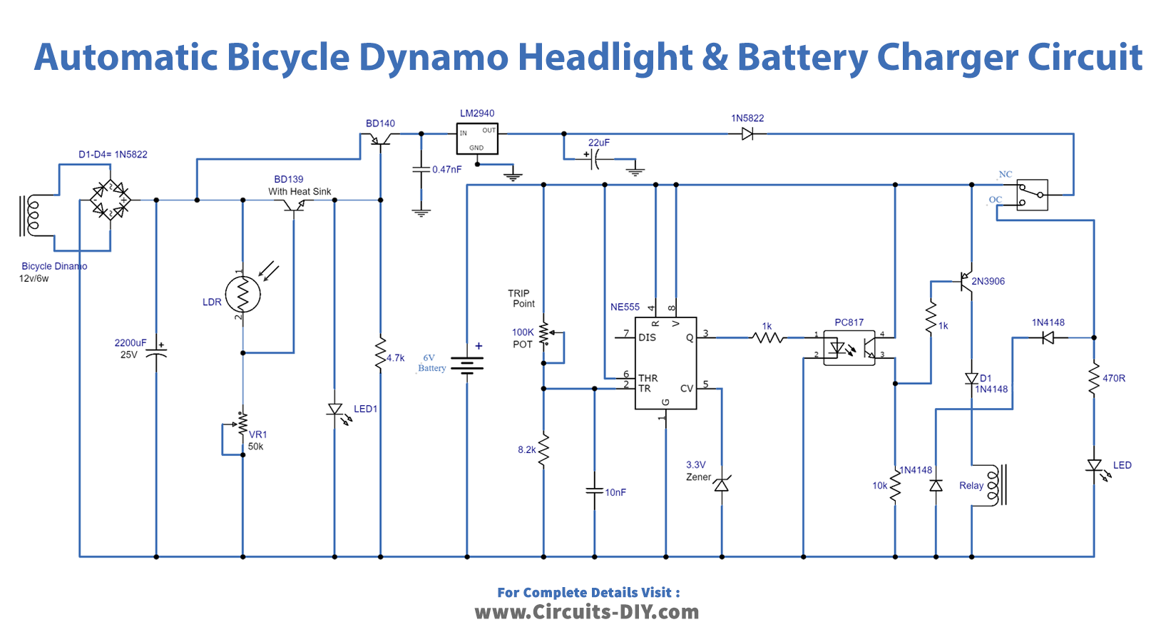
Working Explanation
Since the voltage coming from the dynamo is AC we will convert it into DC through a bridge rectifier which is later filtered through an electrolytic capacitor. A 50K variable resistor is used to adjust the sensitivity of the LDR.
LED1 is on during nighttime. When it is daytime, the LDR will sense the light and it automatically turns off the LED1. Now the voltage will be sent to a voltage regulator IC which will generate a regulated voltage supply for the second part of this circuit.
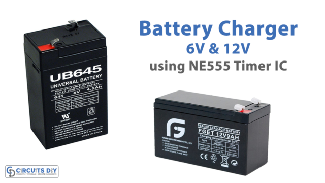
The second portion of this circuit is a charger circuit. It is using a 555 timer IC. The 6V 4.5AH battery gets charged in this portion of the circuit. When the battery gets fully charged the circuit will disconnect with the dynamo automatically and switches the LED2 ON. The second LED is used to indicate the fully charged state of the battery. Since this circuit has these automatic functions, your battery will not overcharge and will have a longer life. During the night this circuit will switch back the dynamo to 12V 6W LED.
Circuit Adjustments
After you are done building this circuit it will need some adjustments initially. To do this you will need a variable power supply.
- First, remove the dynamo supply along with its bridge rectifier and connect a 12V power supply.
- Now cover the LDR with a black solution tape so that it senses dark and adjust the 50K variable resistor until the 6W LED turns ON.
- Remove the battery from the circuit and set the voltage to 7.3 volts in the variable power supply and connect it in the place of the battery.
- Adjust the 100K variable resistor until LED2 turns ON.
- Remove the black tape from LDR and connect the circuit with the dynamo and also the battery.
- For accuracy make sure the circuit is fixed in a suitable enclosure and LDR is enclosed in a small tube attached with it so that the LDR does not receive any light other than daylight.