In this tutorial, we are going to make an “Automatic Smoke Exhaust Fan Circuit”. Many of us have a modular kitchen that has a chimney to extract smoke out so that smell of smoke will not fill in the kitchen and avoids the harmful effects of smoke on furniture and kitchen utensils. But sometimes it happens we forget to switch on the chimney which results in smoke in the kitchen and sometimes we forget to off the chimney leading to the wastage of electricity and money.
So to avoid this situation automatic smoke exhaust fan circuit was developed with readily available components, which will switch on the fan automatically when smoke reaches to point and off the fan. Here we have used MQ-2 Gas/Smoke sensor to detect the smoke. MQ-2 itself is capable of sensing LPG, i-butane, propane, methane, and smoke. Therefore if anyone forgot to open the exhaust system, then this automatic exhaust system circuit automatically detects the gases and smoke. And the exhaust system is automatically started.
Hardware Required
| S.no | Component | Value | Qty |
|---|---|---|---|
| 1. | Gas/Smoke Sensor | MQ-2 | 1 |
| 2. | Diode | 1N4001 | 4 |
| 3. | Step-Down Transformer | 0 to 9V AC | 1 |
| 4. | IC | LM7805 | 1 |
| 5. | IC | LM358 | 1 |
| 6. | Transistor | S8050 | 1 |
| 7. | Resistor | 330Ω,100Ω,10KΩ | 1,1,1 |
| 8. | Capacitor | 470μF/16V,0.1μF | 1,2 |
| 9. | Relay SPDT | 5V | 1 |
| 10. | Variable Resistor | 10KΩ | 1 |
| 11. | LED | – | 1 |
| 12. | Connecting Wires | – | – |
| 13. | Exhaust Fan | – | 1 |
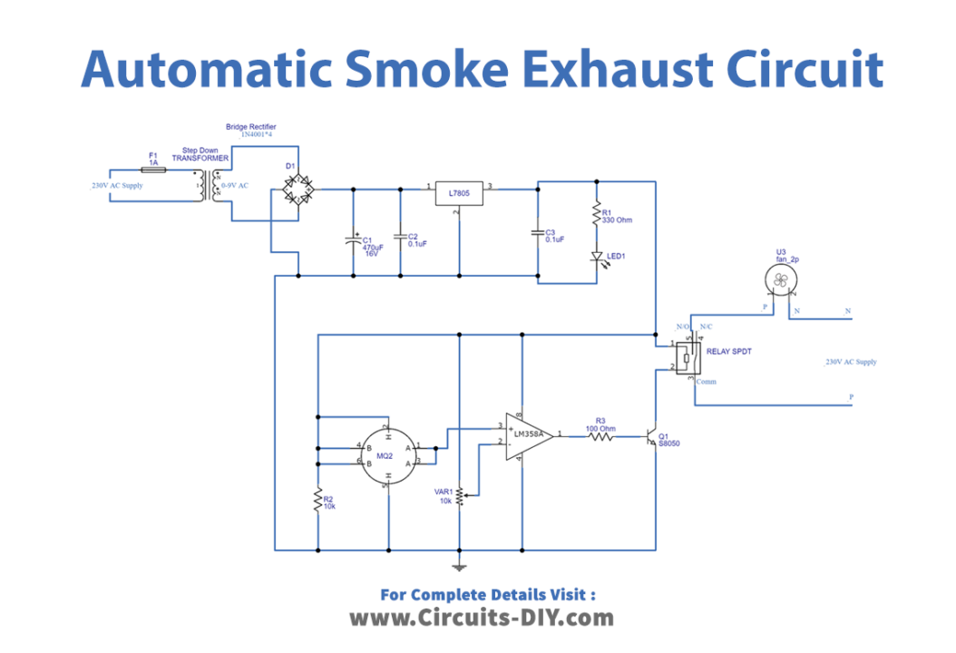
Circuit Diagram
MQ-2 Gas Sensor Pinout

MQ-2 Sensor has good sensitivity to combustible gas and smoke, this sensor uses a heating element to detect smoke. And conductivity of this sensor rises along with the smoke or gas level rising. It has six terminals, two middle terminals are connected to the inner heater component and the others are terminal A and terminal B (sensing element).
S8050 Pinout

This is a three-terminal NPN silicon transistor. S8050 is a low voltage high current small signal NPN transistor, designed for Class B push-pull audio amplifiers and general-purpose applications. It has a maximum gain value of 400, this value determines the amplification capacity of the transistor.
Working Explanation
As we can see in the circuit, we need a 9V supply to operate. So first we have to convert 230V AC to 9V DC. For this, a rectifier is used, and a 230V AC supply is stepped down to 9V AC by using a step-down transformer. Here four 1N4001 diodes are employed to convert the 9V AC supply into a 9V DC supply. Then 470μF C1 capacitor is placed as a filter, which removes the AC ripples in rectified DC. Then a positive voltage regulator, IC 7805 is employed to regulate the 9V DC into 5V DC. LED1 (Green) indicates the power supply status.
Now as we have used MQ-2 Sensor, it has good sensitivity to combustible gas and smoke. It uses a heating element to detect smoke and this sensor’s conductivity rises along with the smoke or gas level rising. Here it has six terminals, two middle terminals are connected to the inner heater component and the others are terminal A and terminal B (sensing element). As the circuit operates with a 9V DC supply, sensor pins B, H, and B are commonly connected to a +9V supply. And the SPDT relay coil is also connected with a +9V supply. Further two sensor terminals, A are connected toward the operational amplifier (LM358) non-inverting input, and another heater terminal H is grounded. Variable resistor VR1 is connected between the +9V DC supply and the variable terminal, which is connected with inverting input of the op-amp. Here this op-amp is configured as a comparator circuit and the sensitivity of this circuit can be varied by VR1. The output of the op-amp is connected to the switching transistor Q1 (S8050) base terminal, this transistor acts as a switch in the relay coil terminal. Hence the collector and emitter will be left open (Reverse biased) when the base pin is held at the ground and will be closed (Forward biased) when a signal is provided to the base pin.
When there is no smoke the op-amp output will be near 0 volts and the Q1 stays in a cutoff or open state, so the relay coil doesn’t get ground supply. If the smoke rises then the op-amp output will rise to 4V and the Q1 becomes a closed-to-turn-on or Active state, so the relay coil gets ground supply. Hence it becomes an electromagnet. When the relay coil gets energized then it attracts a common lever to normally open contact and the supply flows through it. So the exhaust fan runs automatically. Afterward, the fan gets turned off automatically too.
Applications
It can be employed in places such as kitchens, industries, welding shops, commercial kitchens, etc.
Related posts:
 How to make a Joule Thief Circuit
 How to make Audio Amplifier with 2SC5200 Transistor
 Interfacing WS2812b LED Ring with ESP32
 How To Make A Touchless Hand Sanitizer Dispenser - DIY Project
 Sequential Sound Activated Switches - Electronics Project
 Brake Failure Indicator Circuit using 555 Timer - Electronics Project


