Introduction
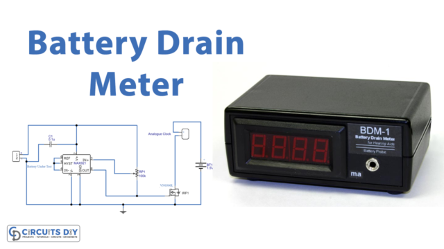
No electronic circuit gadgets and devices without a battery. And, thus it is crucial to keep an eye on the battery. Therefore, it’s only possible by using a battery drain meter. So, in this tutorial, we are going to make the “Battery Drain meter circuit”. Know that, we can use a multimeter too to check if the battery is getting drained, however, this manual method to check the voltage readings coming from the battery is a little time-consuming.
This article will make it simple for you to understand how to check for battery drain by using a simple circuit. The circuit is simple to build, thus just easily available components are needed.
Hardware Required
| S.no | Component | Value | Qty |
|---|---|---|---|
| 1. | IC | MAX921 | 1 |
| 2. | IRF | VN0300L | 1 |
| 3. | Analogue Clock | – | 1 |
| 4. | Potentiometer | 100KΩ | 1 |
| 5. | Ceramic Capacitor | 0.1uf | 1 |
| 6. | Battery | 1.5v | 1 |
| 7. | 2-Pin Connector | – | 1 |
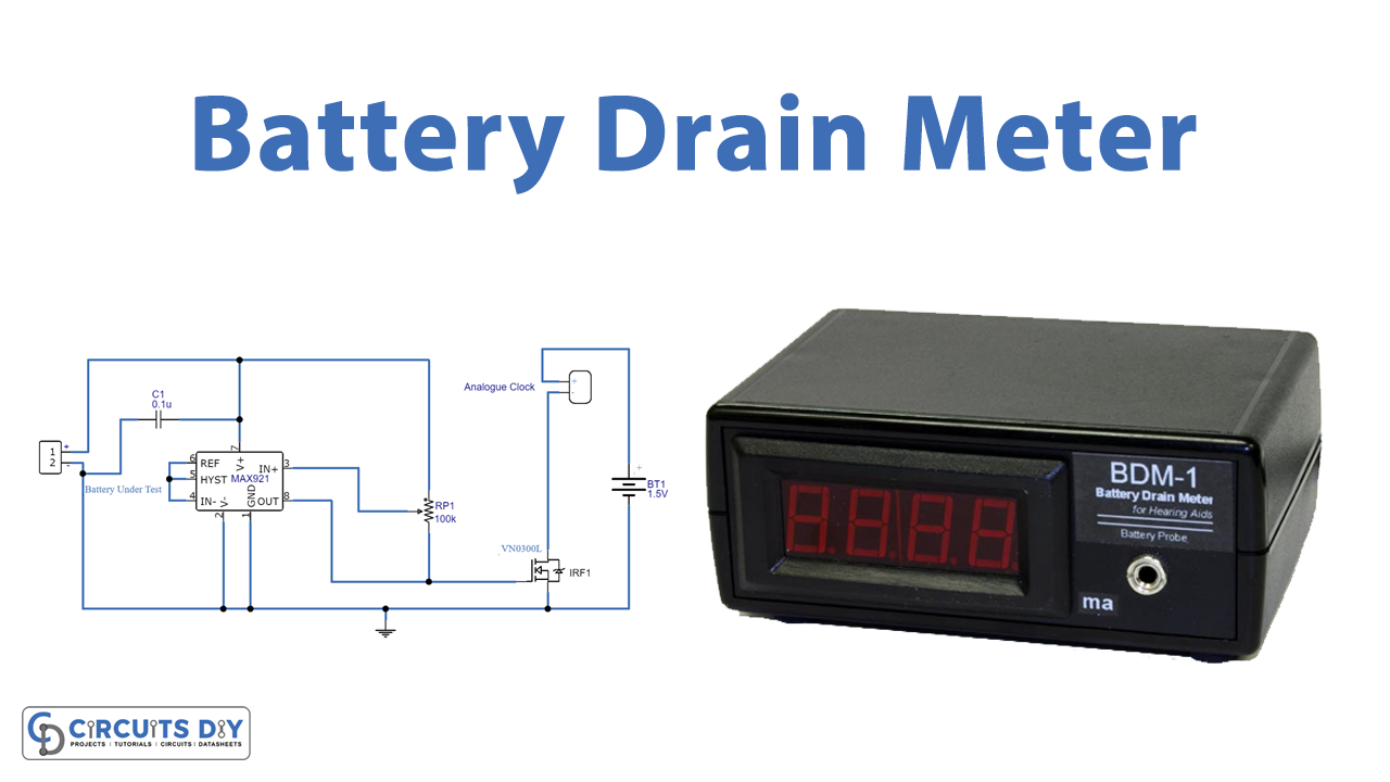
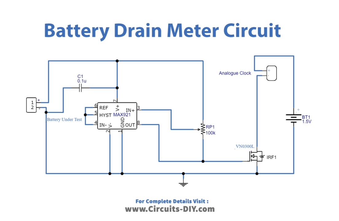
Circuit Diagram
Working Explanation
This Battery Drain Meter Circuit is made up of an analog quartz clock and an integrated circuit called MAX 921. The analog clock is wired with a testing battery and the -Ve terminal of the clock is connected to the drain terminal of a MOSFET. So when the testing battery runs out, the output from MAX 921 is cut off, which causes the drain of the MOSFET to open. Because of this, we can determine the approximate battery drain range by monitoring the analog clock, which stops at a specific hour.
Application and Uses
- Using this circuit, you can figure out what’s wrong with your batteries to fix it.
- To check the car battery drainage.