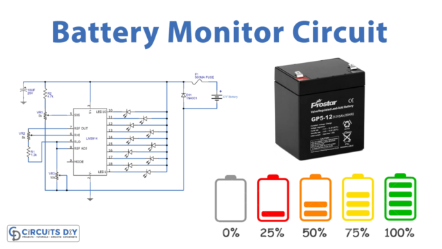
In this tutorial, we are making a Battery High Low monitor. Various batteries ranging from 6 to 12V can be monitored through this circuit. The main component of this circuit is a low-cost LM358 operational amplifier IC. It contains two separate high-gain op-amps in one chip. It has low power consumption and is easy to use.
Hardware Components
The following components are required to make Battery Monitor Circuit
| S.no | Component | Value | Qty |
|---|---|---|---|
| 1. | Battery | – | 1 |
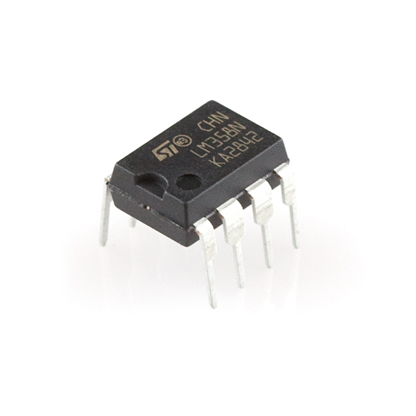
| 2. | Op-Amp IC | LM358 | 1 |
| 3. | Resistor | 10K, 680Ω | 1, 2 |
| 4. | Zener diode | 3V | 1 |
| 5. | LED | 1, 1 | |
| 6. | Variable Resistor | 10K |
LM358 Pinout

For a detailed description of pinout, dimension features, and specifications download the datasheet of LM358
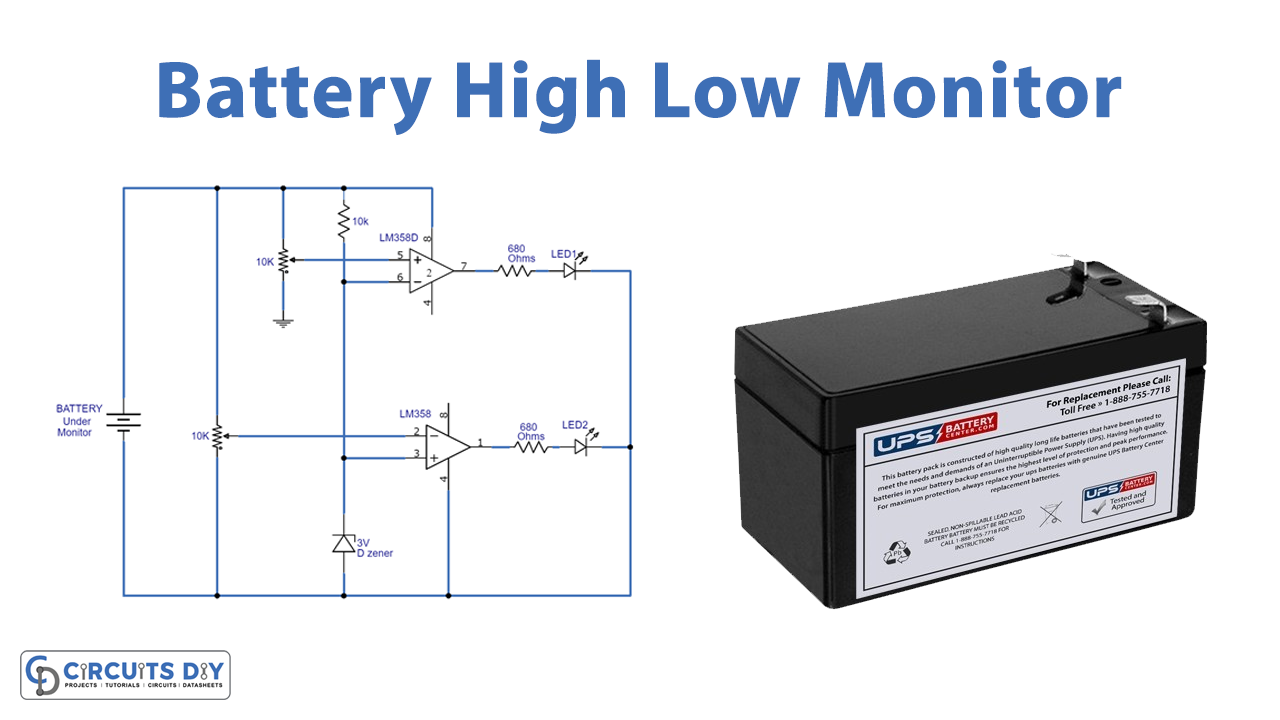
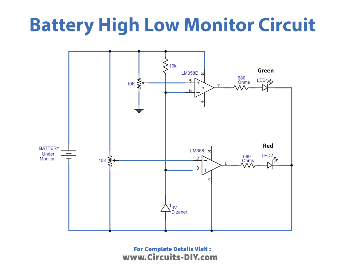
Battery Monitor Circuit
Working Explanation
Both of the operational amplifiers of the LM358 IC are used as comparators to detect the voltage of the battery attached to the circuit for monitoring. They both have a variable resistor of 10K ohms connected at their inputs to adjust the LEDs to go OFF on desired voltages.
Both LEDs will glow indicating the battery is full. When its voltage falls on 12.3V Green LED will go off indicating that the battery is half. Red LED will deactivate when the voltage of the battery falls on 12V indicating that the battery is low and needs to be charged.
Circuit Adjustment
Before using this circuit some adjustments are needed initially. For adjusting this circuit you will need a variable power supply and set its voltage on 12.3V. Replace the battery in this circuit with this variable power supply. Adjust the variable resistor connected with pin 5 of the IC until the green LED turns off. Again change the power supply voltage to 12V and adjust the variable resistor connected with pin 2 of the IC until the red LED turns off.
After these settings do a final test with the circuit. Increase the power supply voltage to 12.6V, both the LEDs should be activated at this voltage. Lower the voltage of the power supply to 12.3V at this voltage green LED should deactivate. Similarly at 12V, the red LED will deactivate. Now your circuit is ready to use.