So we will learn in this project how to create a constant current sink circuit regulated by voltage. A constant current sink device regulated by Voltage, as the name implies, regulates the voltage of the sunk current.
This project is easy to make and requires a few components like Op-amp, PNP Transistor, Shunt Resistor, resistors, Power supply, potentiometer, Bread Board, and additional connecting wires.
Hardware Components
The following components are required to make Constant Current Sink Circuit
| S.no | Component | Value | Qty |
|---|---|---|---|
| 1. | Op-amp | LM358 | 1 |
| 2. | PNP Transistor | BD140 | 1 |
| 3. | Breadboard | – | 1 |
| 4. | Resistor | 1K, 10K, 47 Ohms, 50K Pot | 1, 4, 1, 1 |
| 5. | Power Supply Unit | 12V, DC | 1 |
| 6. | Connecting Wires | Generic | – |
LM358 Pinout

For a detailed description of pinout, dimension features, and specifications download the datasheet of LM358
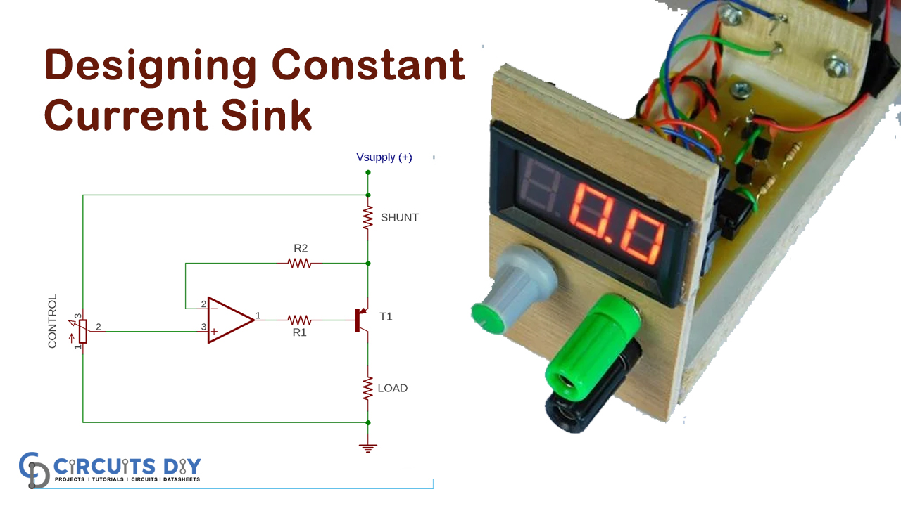
Constant Current Sink Circuit
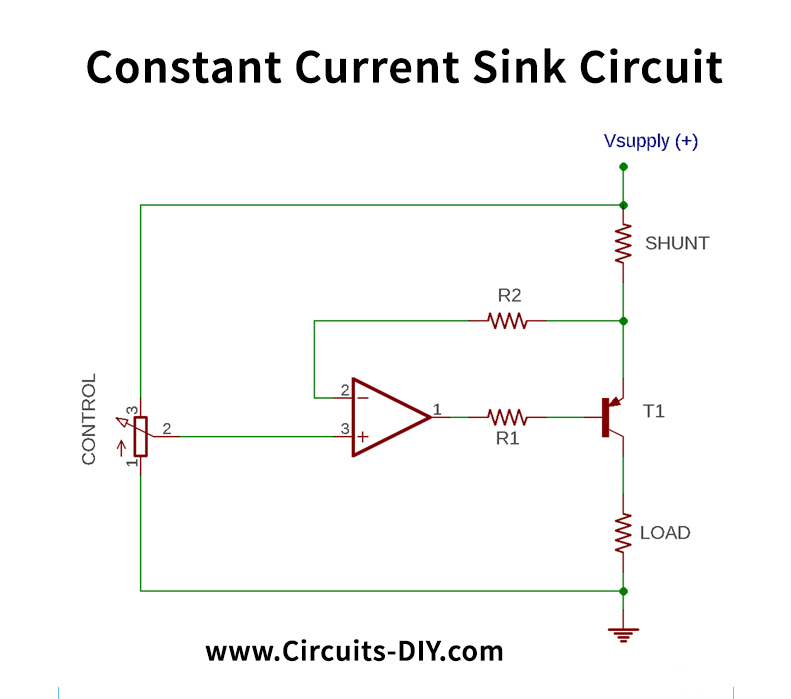
Circuit Operation
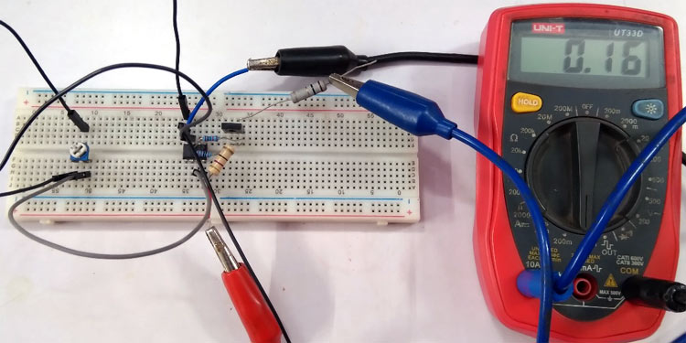
The circuit is made on a basic breadboard as seen in the image below. Different resistors are used as a resistive load to measure the constant current facility.

The input voltage is adjusted with the potentiometer and the load is expressed in the current changes. As seen in the picture below, 0.16A flow is loaded.
As stated earlier, the op-amp would decrease the voltage in its 8V feedback pin via the shunt resistor. The transistor is triggered before the shunt resistor causes an 8V drop. The transistor will turn ON.
Applications and Uses
The Simple Constant Current Sink Circuit is used to regulate the voltage of the sunk current.