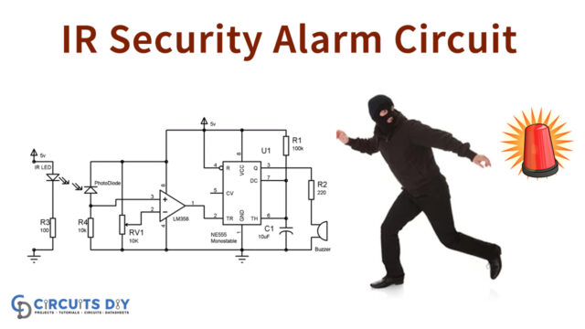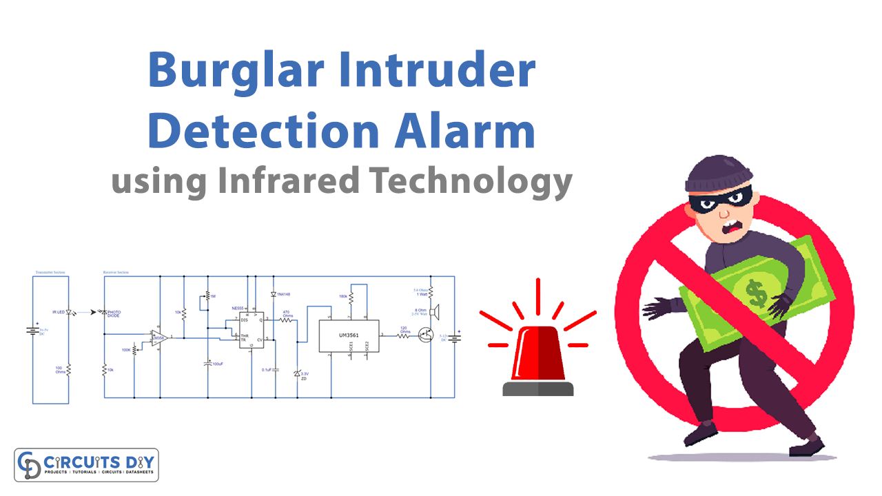
In this tutorial, we are making a project on Burglar / Intruder Detection Alarm using Infrared Technology. This circuit will detect burglary or intrusion at any place either your home or office and activates an alarm to let you know. An invisible infrared beam link is used in this circuit for detection purposes, it is placed where the entry of an intruder is expected like a door or a window.
This circuit has two sections one is the transmitter and the second is the receiver section. There is only an IR LED and a resistor in the transmitter section and it’s operating at 3-5 volts DC. The receiver section has three ICs, one transistor, and other discrete components, it is operating at 5-12V DC.

Hardware Components
The following components are required to make Burglar Detection Alarm Circuit
| S.no | Component | Value | Qty |
|---|---|---|---|
| 1. | IC | NE555 Timer | 1 |
| 2. | IC | UM3561 | 1 |
| 3. | Opamp IC | LM358 | 1 |
| 4. | Photodiode | – | 1 |
| 5. | Variable Resistor | 1M | 1 |
| 6. | Resistor | 100Ω, 10KΩ, 100KΩ, 180KΩ, 470Ω, 120Ω, 5.6Ω/1W | 1 |
| 7. | Transistor | TIP125 | 1 |
| 8. | Zener diode | 3.3V | 1 |
| 9. | Diode | 1N4148 | 1 |
| 10. | LED | – | 1 |
| 11. | Speaker | 8Ω | 1 |
NE555 IC Pinout

For a detailed description of pinout, dimension features, and specifications download the datasheet of 555 Timer
UM3561 Pinout
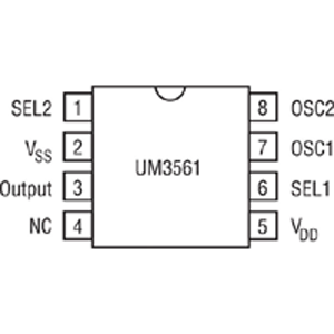
For a detailed description of pinout, dimension features, and specifications download the datasheet of UM3561
LM358 Pinout

For a detailed description of pinout, dimension features, and specifications download the datasheet of LM358
Burglar Detection Alarm Circuit

Working Explanation
The infrared beam is continuously transmitted from IR LED in the transmitter section to the IR receiver. When this contact of beam light and receiver is broken by the entry of a person then the circuit will activate the alarm for a specific time period. This time period is adjusted with a 1M ohms variable resistor.
In order to make this circuit work correctly, proper placement and alignment are required. The IR transmitter and IR receiver should be placed facing each other at a distance of 1 to 10 meters.
Circuit Adjustments
- After the circuit is complete you need to make some adjustments before using it by following these steps
- Set the 1M Variable resistor to its lowest value so the 555 timers will activate the alarm only for a few seconds
- Adjust the 100K VR for the maximum distance between the IR transmitter and receiver LEDs
- Set the 1M VR at the required time period of alarm activation.
- Now the circuit is ready to use.