Introduction
The need for a security system has arisen as a result of rising crime rates. So, Having a security system gives you the safety and security you need to lead a peaceful life, whether it be at your house, place of employment, or apartment. All fields of life are gradually introducing new technologies. However, modern tools and devices need to be improved and changed to improve security. Thus in this article, we will make a modern Laser Tripwire Home Alarm System.
You might have played with laser toy guns in your childhood, or you may have seen the laser in various science fiction movies. And, you might have also seen the laser maze challenge game, in which when a person touches the laser, an alarm produces a sound. The same things happen in the laser tripwire alarms.
What is Laser Tripwire?
As the name indicates, Laser Tripwire employs laser technology to give a safety system to the user. Laser tripwire enables you to cover the whole area or site with such a laser security system using a variety of light beams.
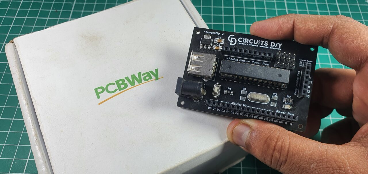
This Project is sponsored by PCBWay. They have an open-source community, people can share their design projects with each other. Moreover, every time people place an order for your board, PCBWay will donate 10% of the cost of PCB to you, for your contribution to the Open Source Community.
Hardware Components
You will require the following hardware for the Laser Tripwire Home Alarm System.
| S.no | Component | Value | Qty |
|---|---|---|---|
| 1. | Arduino UNO | – | 1 |
| 2. | LDR | – | 1 |
| 3. | Laser Source | – | 1 |
| 4. | Buzzer | – | 1 |
| 5. | LED | – | 1 |
| 6. | Resistor | 10KΩ | 1 |
| 7. | Breadboard | – | 1 |
| 8. | Jumper Wires | – | 1 |
Steps for Making Laser Tripwire Alarm
The components of a Laser Tripwire Home Alarm System are very basic. The table above lists all of the components. Once you have got those components, proceed as follows:
Schematic
Make connections according to the circuit diagram given below.
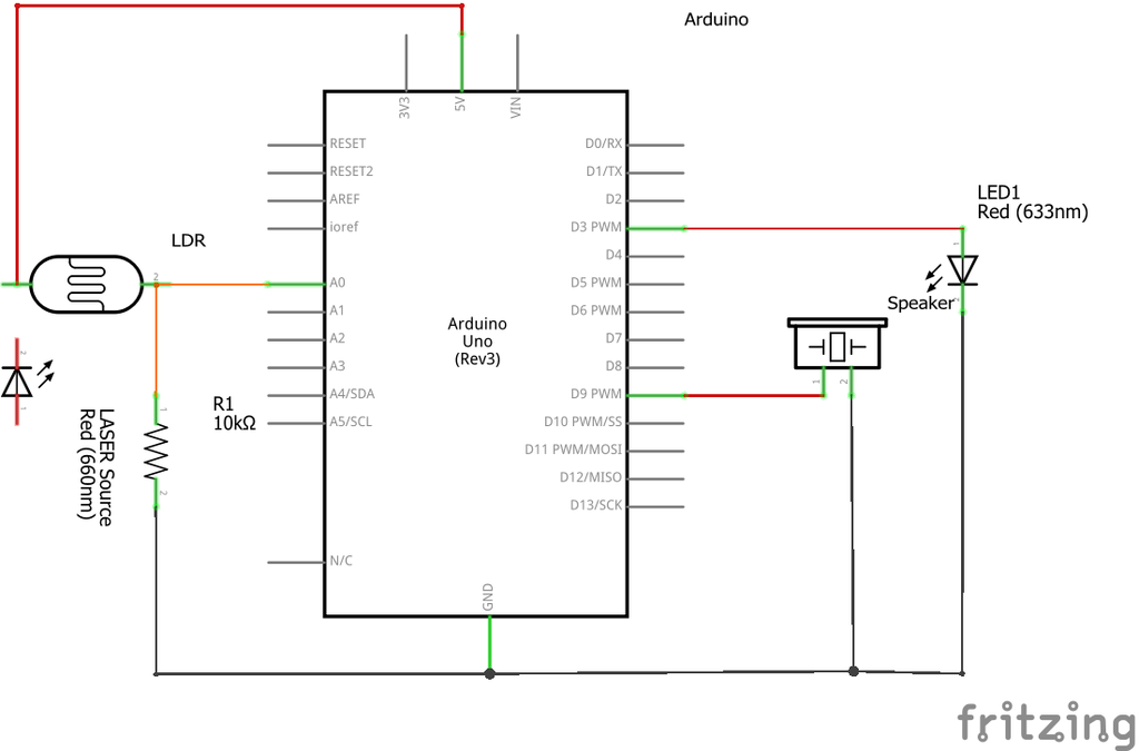
Wiring / Connections
| Arduino | LDR | Buzzer | LED |
|---|---|---|---|
| 5V | 1st Pin | ||
| GND | 2nd Pin with R1 | -Ve | -Ve |
| A0 | 2nd Pin | ||
| D9 | +Ve | ||
| D3 | +Ve |
Installing Arduino IDE
First, you need to install Arduino IDE Software from its official website Arduino. Here is a simple step-by-step guide on “How to install Arduino IDE“.
Code
Now copy the following code and upload it to Arduino IDE Software.
const int buzzerPin = 9;
int led = 3;
void setup() {
Serial.begin(9600);
pinMode(buzzerPin, OUTPUT);
pinMode(led, OUTPUT);
}
void loop() {
int sensorValue = analogRead(A0);
Serial.println(sensorValue);
while(sensorValue < 800){
tone(buzzerPin, 50);
delay(50);
noTone(buzzerPin);;
digitalWrite(led, HIGH);
delay(100);
digitalWrite(led,LOW);
}
delay(100);
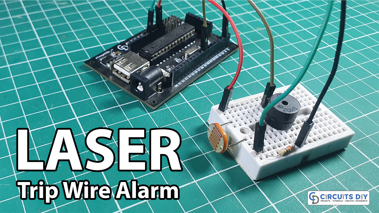
}Let’s Test It
It’s now time to test the circuit. Power up the Arduino while the laser is incident on the LDR. Now place your hand in front of laser, and the buzzer will start to beep
Working Explanation
To understand the circuit, let’s dig into the code:
- First, we define the Arduino pins that are connected to the buzzer and LED. Also, we name those pins as buzzerPin and Led
- In the void setup, we first initialize the serial monitor. After that, we declare both led and buzzer pins as output.
- In the void loop, we provide the function analogRead(A0) to read the values coming from pin A0 which is connected to the LDR. Thus, we store that value in the integer variable sensorValue. Then we give a while condition to provide a buzzer to make a sound when the value exceeds from 800. Also, use the digitalWrite function to make LED high.
The operation is easy. When the Laser is incident on the LDR, The Arduino reads and stores the values of the LDR. When someone passes across the laser, the LDR value changes, causing an alert to sound by activating the Buzzer. It will keep going until you manually press the reset button given on the Arduino.
Applications
- Intruder alarms
- Home and workplace security systems; etc
Conclusion.
We hope you have found this Laser Tripwire Home Alarm System Circuit very useful. If you feel any difficulty in making it feel free to ask anything in the comment section.