While making different electronic projects you need to pick crystals of the right frequency. In order to do that you need a Crystal Tester Circuit that we are about to demonstrate. A crystal tester circuit also known as xtal tester circuit is used to check whether a crystal element is working fine or not. Many circuits and projects use crystals as an important element. Crystals are used to oscillate signals, for that we need these crystals to work properly. This tester circuit will also form an oscillator circuit and if the crystal will be working fine we will know through the blinking of LED.
This circuit is using only a handful of common components like transistors, diodes, capacitors, resistors and an LED.
Hardware Components
| S.no | Component | Value | Qty |
|---|---|---|---|
| 1. | DC Supply | 6V | 1 |
| 2. | Transistor | BC548 | 2 |
| 3. | Diode | 1N914 | 2 |
| 4. | LED | – | 1 |
| 5. | Resistor | 47KΩ, 2.2KΩ, 10KΩ, 1KΩ | 1, 1, 1, 1 |
| 6. | Capacitor | 1nF, 100pF, 0.1µF | 2, 1, 1 |
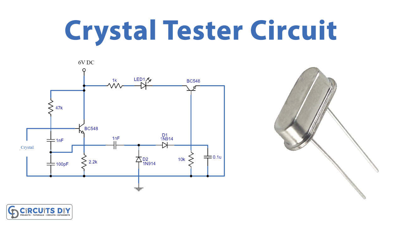
Circuit Diagram

Working Explanation
This circuit is using two BC547 capacitors which are connected together. The crystal is directly connected to the base of transistor T1. When the crystal provides oscillator signals it will activate T1 this output will be rectified by 1N914 diodes. Then later filtered by capacitors before reaching transistor T2. When T2 receives this signal it will activate. T2 drives the LED if the LED glows it means that the crystal is working fine.
If the LED isn’t glowing it shows that the crystal under test might be damaged or faulty. The operating voltage of this circuit is 6 volts. Resistors are used before each component to limit the current.
Applications and Uses
There are a lot of electronic projects working with high-frequency equipment. They utilize crystals to generate frequencies of oscillator circuits. Using this circuit you can test and verify the operation of any crystal.