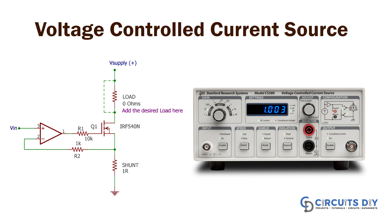
In this project, we will demonstrate how to build an op-amp-based voltage-controlled current source to see how it works. The current servo is also called this type of voltage-regulated power source circuit. The circuit is very convenient and can design with a minimal number of components.
In electronics, this type of circuit is also used to drive devices with current power, such as BJT, SCR, etc. We know that in a BJT, the current flow is controlled through the transistor base when the transistor is closed, and several kinds of circuits can give this base current. The current circuit that can also be used to drive electrical operated devices can also be checked.
Hardware Components
The following components are required to make Voltage Controlled Current Source Circuit
| S.no | Component | Value | Qty |
|---|---|---|---|
| 1. | Op-amp IC | LM358 | 1 |
| 2. | MOSFET | IRF540N | 1 |
| 3. | Shunt Resistor | 1 ohm | 1 |
| 4 | Resistor | 1K, 10K | 1, 1 |
| 5. | Power supply | 12V | 1 |
| 6. | Power supply unit | – | 1 |
| 7. | Bread Board | – | 1 |
LM358 Pinout

For a detailed description of pinout, dimension features, and specifications download the datasheet of LM358
Voltage Controlled Current Source Circuit
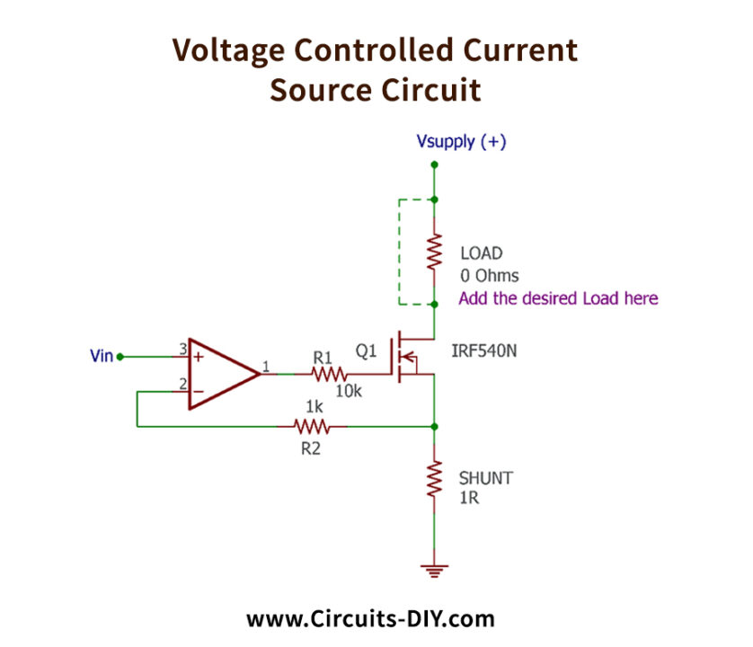
Circuit Operation
As you can see in this image, the circuit is built into a breadboard for testing purposes. The load is not attached to the circuit to ensure the current regulation is measured by an almost perfect 0 Ohm (shorted).
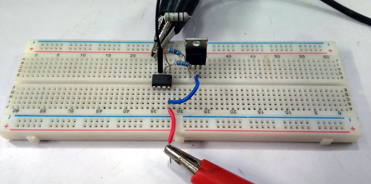
The current shifts on the other channel will mirror, and the input voltage changes to 0. 5V from 0.1. As you can see in this picture, the second channel to draw 400mA current at 9V output is essentially 0.4V input with 0 current draws. A 9V supply uses to power the circuit.

Applications and Uses
Voltage Controlled Current Source Circuit is widely used in electronics to drive devices such as BJT, SCR, and so on.