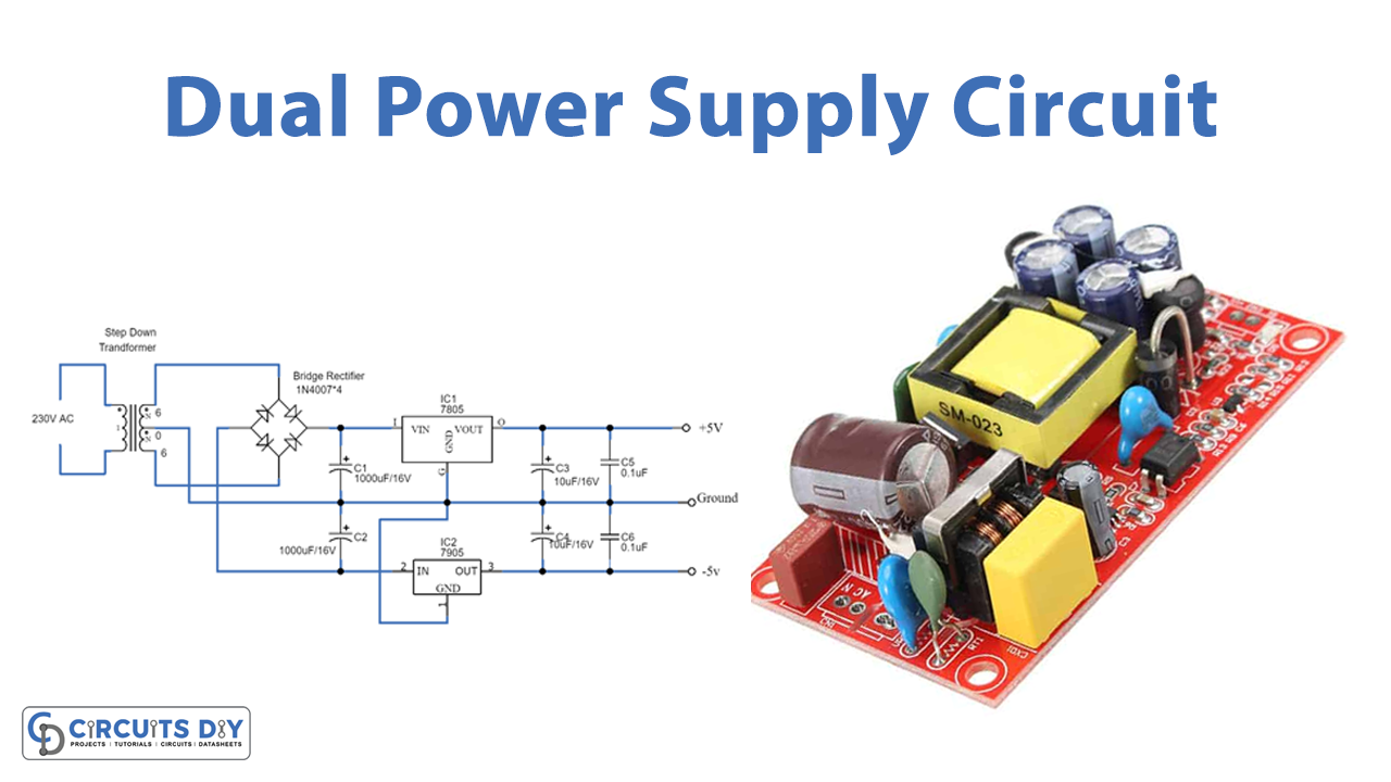
In this tutorial, we are going to make a “Dual Power Supply Circuit”.
A dual power supply is a regular direct current power supply, it can provide a positive as well as a negative voltage. It also ensures a stable power supply to the device as well as helps to prevent system damage. As there are some particular applications where we need both a positive and a negative voltage of the same magnitude at the same time that is where the dual power supply is a convenient option. For example, op-amps generally need to swing bipolar output voltages, and when we want to run two different power circuits on the same power supply without taking it offline It helps the device to function properly and secure from damage to the assembled equipment. Here we design a dual power supply circuit by using a step-down transformer and linear voltage regulators.
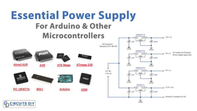
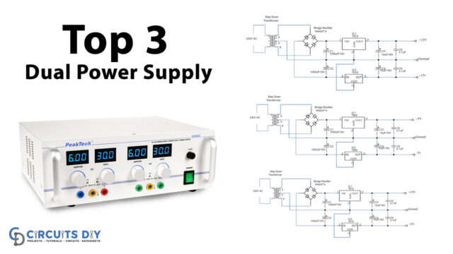
Mostly we see electronic circuits and applications operate in the DC voltage range that falls in 5, 12, and 15 Volts, therefore we are going to make three types of dual power supply circuits. All circuits have individual step-down transformers and voltage regulators, if you want you may include an LED indicator. Circuits are listed as,
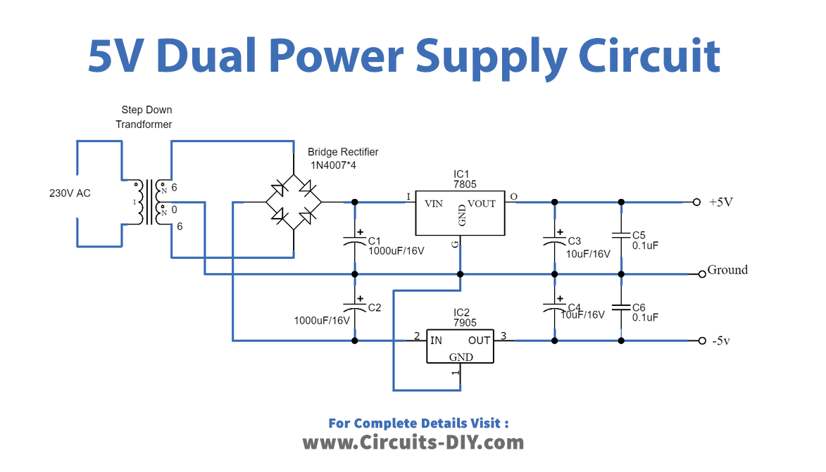
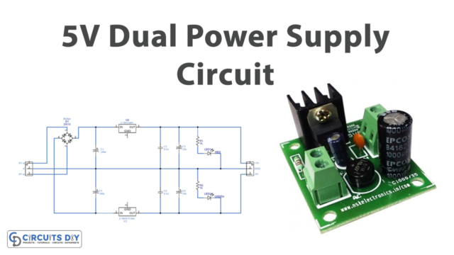
- 5 Volt Dual power supply circuit
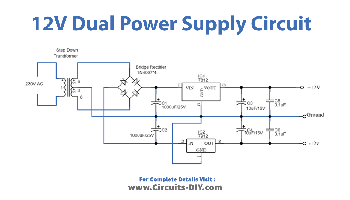
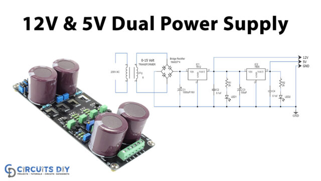
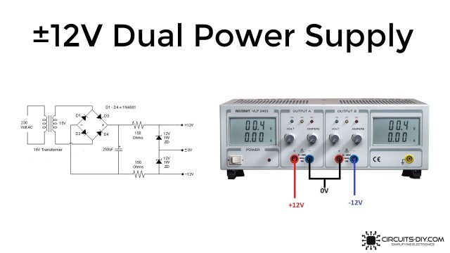
- 12 Volt Dual power supply circuit
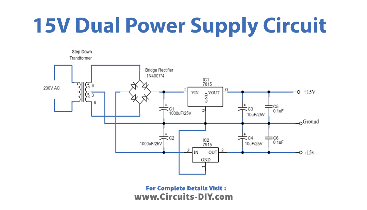
- 15 Volt Dual power supply circuit
Hardware Components
The following components are required to make a Dual Power Supply Circuit
| S.o | Component | Value | Qty |
|---|---|---|---|
| 1. | Step down Transformer | 6V-0-6V | 1 |
| 2. | Diode | 1N4007 | 4 |
| 3. | Electrolyte Capacitor | 1000uF, 10uF | 2, 2 |
| 4. | Regulator IC | LM7805, 7905, 7812, 7912, 7815, 7915 | 1,1 |
| 5. | Ceramic capacitor | 0.1uF | 2 |
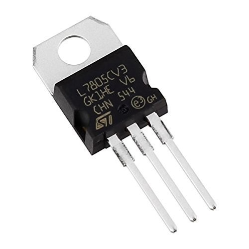
7805 Pinout
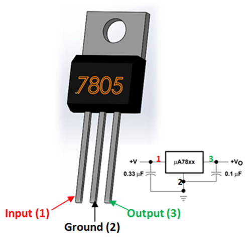
For a detailed description of pinout, dimension features, and specifications download the datasheet of 7805
7812 Pinout
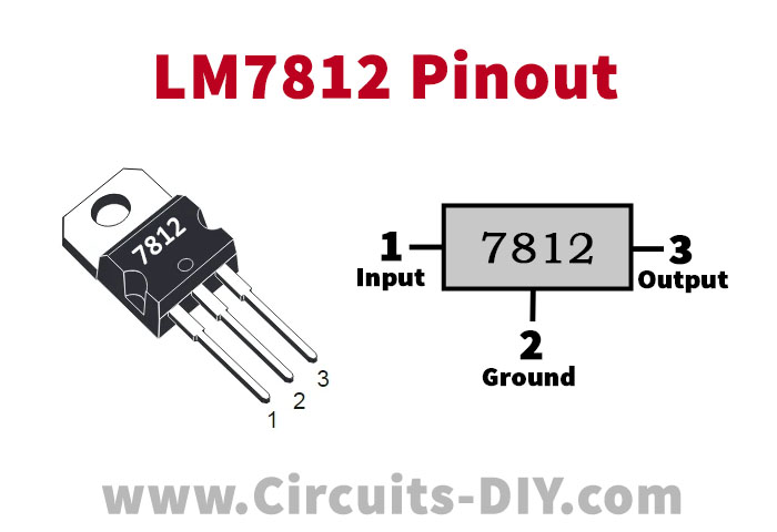
For a detailed description of pinout, dimension features, and specifications download the datasheet of 7812
7815 Pinout
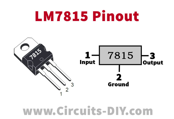
For a detailed description of pinout, dimension features, and specifications download the datasheet of 7815
Dual Power Supply Circuit
Working Explanation
If we understand one circuit working, it means you understand all above three dual power supply circuit construction and working because methods are the same only the component’s specifications changes, which depends on the output voltage range.
As we can see dual power supply circuit has four stages. Stage-I: converting 220v AC into 12v AC including step down transformer, stage – II: converting 12v AC into 12v DC including full bridge rectifier stage -III: filter the ripples from the output include then stage -IV: regulate the 12v DC power supply include regulator ICs (Voltage Regulator 78XX is responsible to regulate the positive side of DC voltage and 79XX is responsible to regulate the negative side of DC Voltage).
Here the primary terminals of the center-tapped transformer are connected with household supply (230V ac, 50Hz), and output is taken from the secondary terminals of the transformer. The advantage of using a center-tapped transformer is we can get both +V and -V dc supply using only one transformer. Step down transformer reduces the amplitude of input AC 230 volt to 5-0-5 Vac or 12-0-12 Vac or 15-0-15 Vac depending on its specification.
The outer two terminals of the center-tapped transformer are connected to the bridge rectifier circuit. The rectifier circuit is a converter, which converts ac supply into dc supply. It is generally made up of diode switches. In this dual power supply circuit, the diode bridge rectifier is made up of four power diodes. Low voltage AC supply from the secondary winding of the transformer is fed into the bridge rectifier module (1N4007 X 4), the output of the rectifier is not pure dc, it contains ripples in it.
Now, dc output which contains peak-to-peak ripples can’t be connected directly to the load. So, to remove ripples from the supply, filter capacitors are used. Here two filter capacitors C1 and C2 are used. The connection of both capacitors is such that the common terminal of the capacitors is connected directly to the center terminal of the center-tapped transformer. These capacitors will get charged up to the needed dc as both are connected with the common terminal of a transformer. Furthermore, the capacitors will remove the ripples from the dc supply and give a pure dc output. C1 capacitor in all circuits filters the positive side and the C2 capacitor filters the negative side. But, the output of both the capacitors is not regulated. So, to make the supply regulated, the output of the capacitors is given to the voltage regulator ICs. If we required output voltage is +5V, then 7805 IC is used if we need the output voltage +12V then IC 7812 is used. The last two digits of the IC give an output voltage rating. The third last digit shows voltage is positive or negative. For positive voltage (8) and negative voltage (9) number is used. So IC7812 is used for +12v regulation and IC7912 is used for -12v voltage regulation. The ground terminal of both ICs is connected with the center tap terminal of the transformer to create a reference. Now, the output voltages are measured between the output terminal and ground terminal for both ICs. On the output side capacitors, C3 and C4 remove any kind of ripples in DC supply, and capacitors C5 and C6 remove high-frequency ripples if any at the positive and negative sides of DC output. The common ground supply is derived directly from the center tap of the transformer (0) and acts as a Ground (GND) terminal for +V and -V DC supply output.
Applications
In DIY, we can use a dual power supply as a cell phone charging circuit, power bank circuit, battery-less power circuit, and also in case of any direct current power supply.


Where does on get the pc board layout for these