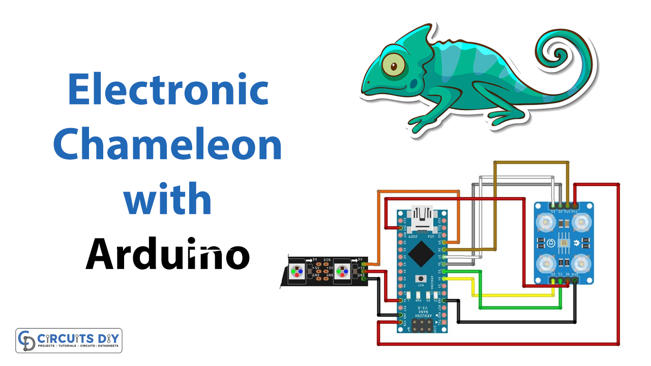
Introduction
Do you want to learn Arduino in a fun way? Let’s look at this project. Because in this project using an Arduino and a color sensor, we are making an electronic chameleon
We are all familiar with chameleons. Since we already know that they have the unique ability to alter their color in response to their surroundings, They employ this skill to both capture their prey and flee from predators. Don’t worry! we don’t have any prey to make this electronic chameleon. And, if there is any it is only you because we want you to learn electronics. So let’s get started!
What is Electronic Chameleon?
As the name implies, it’s a device that would sense and changes color accordingly. And for this, they employ color sensors. A color sensor is a sort of “photoelectric sensor” that uses a transmitter to generate light and a receiver to detect the light that is reflected from the object being detected
Hardware Components
You will require the following hardware for Electronic Chameleon.
| S.no | Component | Value | Qty |
|---|---|---|---|
| 1. | Arduino UNO | – | 1 |
| 2. | Color Sensor | TCS230 | 1 |
| 3. | RGB LED | WS2812 | 1 |
| 4. | Breadboard | – | 1 |
| 5. | Jumper Wires | – | 1 |
Steps for Making an Electronic Chameleon
To make this electronic chameleon, grab all the above-given components and then follow the given steps:
Schematic
Make connections according to the circuit diagram given below.
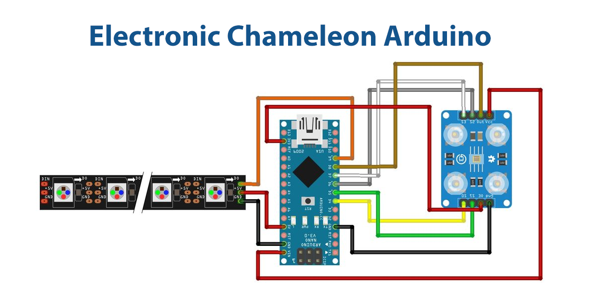
Wiring / Connections
| Arduino | Color Sensor | RGB Strip |
|---|---|---|
| 5V | VCC | VCC |
| 3.3v | 3v | |
| GND | GND | GND |
| D4 | S0 | |
| D5 | S1 | |
| D6 | S2 | |
| D7 | S3 | |
| D8 | OUT | |
| D9 | D0 |
Installing Arduino IDE
First, you need to install Arduino IDE Software from its official website Arduino. Here is a simple step-by-step guide on “How to install Arduino IDE“.
Installing Libraries
Before you start uploading a code, download and unzip the following libraries at /Progam Files(x86)/Arduino/Libraries (default), to use the sensor with the Arduino board. Here is a simple step-by-step guide on “How to Add Libraries in Arduino IDE“.
Code
Now copy the following code and upload it to Arduino IDE Software.
#include <Adafruit_NeoPixel.h>
#ifdef __AVR__
#include <avr/power.h>
#endif

 // Which pin on the Arduino is connected to the NeoPixels?
#define PIN      9

 // How many NeoPixels are attached to the Arduino?
#define NUMPIXELS 5

Adafruit_NeoPixel pixels = Adafruit_NeoPixel(NUMPIXELS, PIN, NEO_GRB + NEO_KHZ800);

int delayval = 333; // delay

#define S0 4
#define S1 5
#define S2 6
#define S3 7
#define sensorOut 8

int frequency = 0;
int Red, Green, Blue;

void setup() {
  pinMode(S0, OUTPUT);
  pinMode(S1, OUTPUT);
  pinMode(S2, OUTPUT);
  pinMode(S3, OUTPUT);
  pinMode(sensorOut, INPUT);

  // Setting frequency-scaling to 20%
  digitalWrite(S0,HIGH);
  digitalWrite(S1,LOW);

  Serial.begin(9600);
  pixels.begin(); // This initializes the NeoPixel library.
}

void loop() {
  // Setting red filtered photodiodes to be read
  digitalWrite(S2,LOW);
  digitalWrite(S3,LOW);
  // Reading the output frequency
  frequency = pulseIn(sensorOut, LOW);
  //Remaping the value of the frequency to the RGB Model of 0 to 255
  frequency = map(frequency, 25,72,255,0);
  if (frequency < 0) {
    frequency = 0;
  }
  if (frequency > 255) {
    frequency = 255;
  }
  Red= frequency;
  // Printing the value on the serial monitor
  Serial.print("R= ");//printing name
  Serial.print(frequency);//printing RED color frequency
  Serial.print("  ");
  delay(100);

  // Setting Green filtered photodiodes to be read
  digitalWrite(S2,HIGH);
  digitalWrite(S3,HIGH);
  // Reading the output frequency
  frequency = pulseIn(sensorOut, LOW);
  //Remaping the value of the frequency to the RGB Model of 0 to 255
  frequency = map(frequency, 30,90,255,0);
  if (frequency < 0) {
    frequency = 0;
  }
  if (frequency > 255) {
    frequency = 255;
  }
  Green = frequency;
  // Printing the value on the serial monitor
  Serial.print("G= ");//printing name
  Serial.print(frequency);//printing RED color frequency
  Serial.print("  ");
  delay(100);

  // Setting Blue filtered photodiodes to be read
  digitalWrite(S2,LOW);
  digitalWrite(S3,HIGH);
  // Reading the output frequency
  frequency = pulseIn(sensorOut, LOW);
  //Remaping the value of the frequency to the RGB Model of 0 to 255
  frequency = map(frequency, 25,70,255,0);
  if (frequency < 0) {
    frequency = 0;
  }
  if (frequency > 255) {
    frequency = 255;
  }
  Blue = frequency;
  // Printing the value on the serial monitor
  Serial.print("B= ");//printing name
  Serial.print(frequency);//printing RED color frequency
  Serial.println("  ");
  pixels.setPixelColor(0, pixels.Color(Red,Green,Blue)); // Moderately bright green color.
  pixels.setBrightness(64);
  pixels.show(); // This sends the updated pixel color to the hardware.
  delay(100);
}
Let’s Test It
It’s now time to test the circuit. Once you upload the code, power up the Arduino. It can now accurately replicate any colors you would show the sensor. Additionally, the values would be printed on a serial monitor.
Working Explanation
Let’s dig into the coding to understand the working of the circuit:
- At first, we include all the required libraries
- Define Arduino pins connected with neo-pixel LED. And, make an adafruit object for that.
- Then define the Arduino pins that are connected to the sensor. Also, define the pin of the Arduino that will provide an output value. In our case, we choose pin 8 Make an integer variable ‘frequency’ to store the frequency which is 0 initially. Also, make three more variables and name the Red, Blue, and Green.
- Now, coming towards the void setup, here first declare the status of sensor pins that are connecteArduinoduino as input and declare sensorOut (pin 8 ) as output. Then to set the frequency scale to 20% make the sensor pin S0 high and S1 as low. Then we initialize the serial monitor and neo-pixel library.
- In the void loop, we give different combinations of high and low to the pins for photodiodes to read red, green, or blue color. To read the frequency we give the pulseIn function and store that in the frequency variable. The frequency value is remapped to the RGB Model, which ranges from 0 to 255.
- We print the values on the serial monitor.
Applications
- Ambient lighting
- Room Lightning
- DIY projects
Conclusion.
We hope you have found this Electronic Chameleon Circuit very useful. If you feel any difficulty in making it feel free to ask anything in the comment section.