In this tutorial, we are demonstrating a project of an FM Radio Receiver using TDA7000. TDA7000 is a well-known FM radio receiver IC additionally called a one-chip FM radio receiver that covers the VHF FM band from 70 to 120 MHZ. This IC was first presented in the 1980s and increased its fame in the electronics world and it is still well known following 31 years. The principal reason for its fame is that all the complicated electronics of an FM receiver like input RF stage, IF filter stage, local oscillator stage, IF limiter stage, Frequency locked loop framework, and so forth have been worked inside the IC, in this manner, the IC require just a couple of external parts to make a good quality FM radio receiver with the sensitivity of 1.5µV.
Although the IC has been ended by the maker in 2004 however it is still in a load of some electronic merchants so you need to look through it on the web or at your neighborhood electronic market on the off chance that you require one. On the off chance that you cannot discover the IC, at that point you can likewise utilize its other substitute which is TDA7010T. The inner circuit of this IC is practically like TDA7000 just the difference is that TDA7010T is a surface mount version (SMD) and comes in 16 pins.
Hardware Components
The following components are required to make an FM Receiver Circuit
| S.no | Components | Value | Qty |
|---|---|---|---|
| 1 | IC | TDA7000 | 1 |
| 2 | Coil | 6 turns, 5 Turns | 1, 1 |
| 3 | Capacitor | 3.3nF, 180pF, 330pF, 150pF, 220pF, 68pF, 100nF, 22nF, 82pF, 1.8nF, 10nF, 27pF, 2.2mF, 22pF | 2, 1, 2, 1, 2, 1, 2, 1, 1, 1, 1, 1, 1, 1 |
| 4 | Variable Capacitor | 15-30pF | 1 |
| 5 | Resistor | 10k, 22K | 1, 1 |
| 6 | Battery | 5V | 1 |
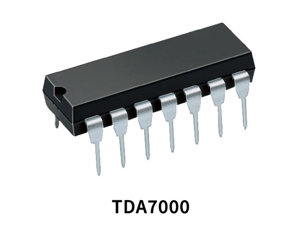
TDA7000 Pinout
For a detailed description of pinout, dimension features, and specifications download the datasheet of TDA7000
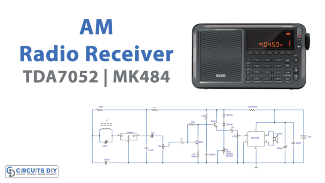
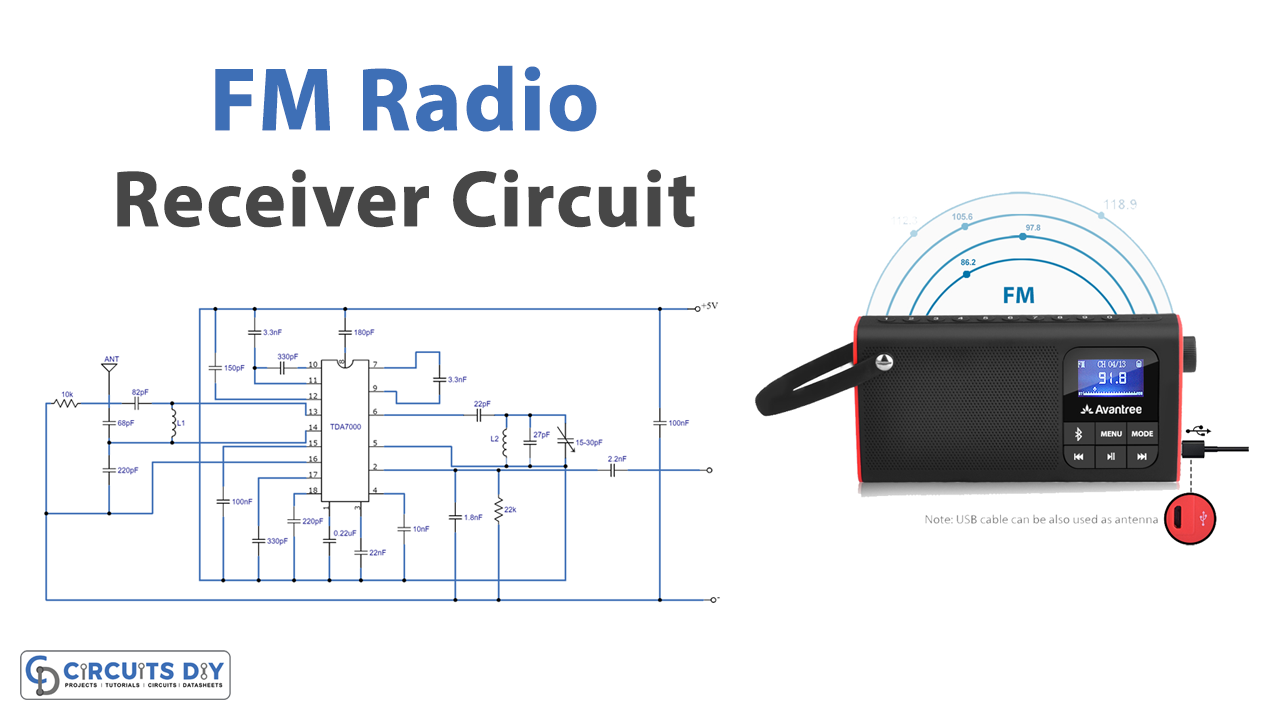
FM Receiver Circuit

Working Explanation
The circuit referenced here is utilizing two coils L1 and L2. L1 is equivalent to 6 turns of enameled copper wire of 23 SWG close coiled on a 3mm measurement air core. Furthermore, L2 is equivalent to 5 turns of 23 SWG wire close coiled on 3mm distance across the structure air core. Utilize a small variable capacitor or trimmer in the spot of VC1. Utilize adjustable receiving wire or 80cm wire as a reception apparatus. The stock voltage can be between 3V to 10V DC. You can likewise utilize any sound amplifier IC with the circuit to drive a speaker.
Applications and Uses
The FM Radio Receiver is used in FM Radio Broadcasting. It is also used in telemetry, radar, etc.