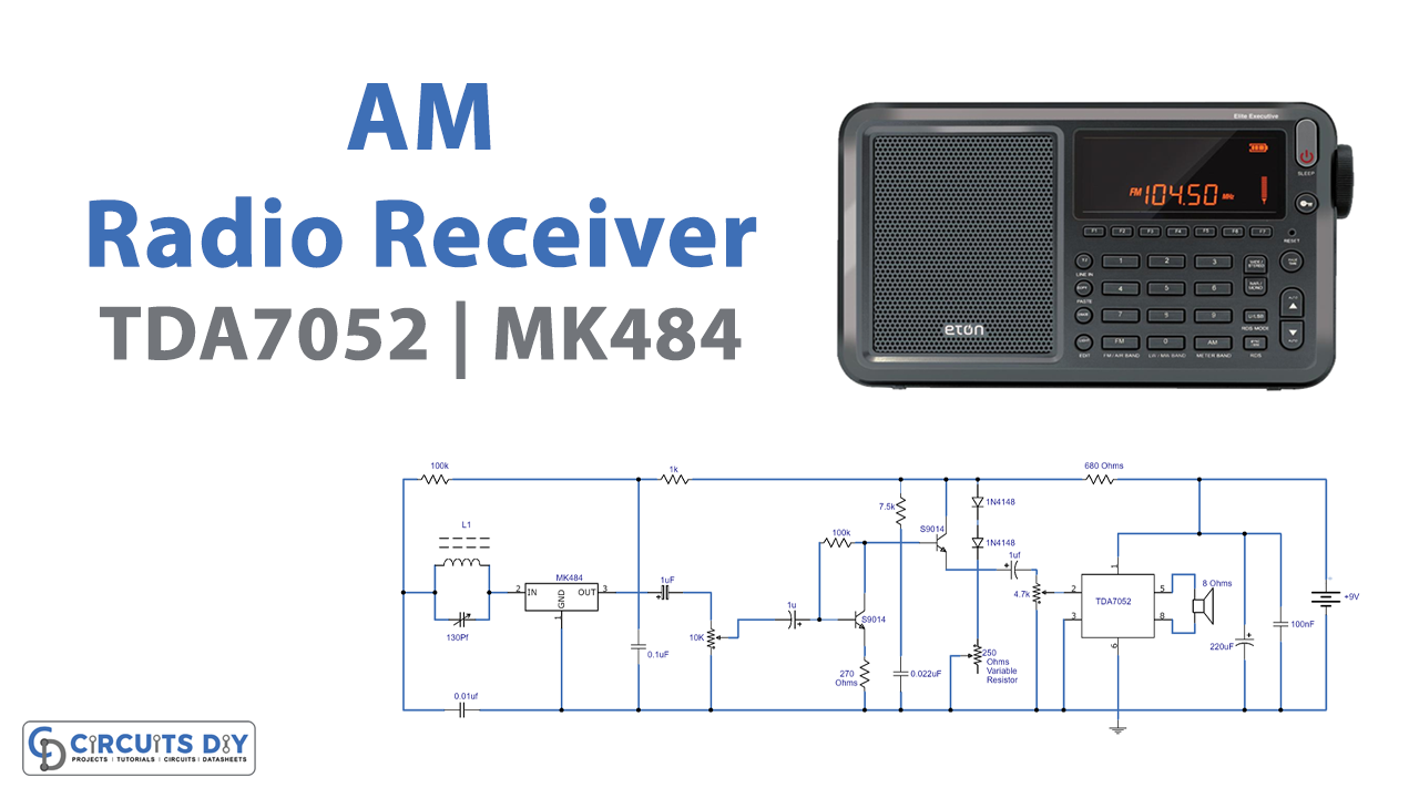
The circuit demonstrated here is an MK484 AM radio receiver with a TDA7052 Amplifier. ZN414 IC has been discontinued scarcely any years prior and now MK484 and TA7642 AM receiver ICs have ruled out the market. The internal hardware of these ICs is similar to ZN414 but has amazing features that were absent in ZN414. Furthermore, these are available in the TO-92 package.
These ICs contain AM radio circuits and require just a few external components to drive the circuit. It utilizes two 9014 transistors for driving earphones. Additionally, we have made further upgrades to the circuit and connected a TDA7052 amplifier IC for driving an 8 ohms speaker.
Hardware Components
The following components are required to make AM Radio Circuit
| S.no | Components | Value | Qty |
|---|---|---|---|
| 1. | AM radio receiver | MK484 | 1 |
| 2. | IC | TDA7052 | 1 |
| 3. | Transistor | 9014 | 2 |
| 4. | Inductor | 55 turns | 1 |
| 5. | Speaker | 8 ohms | 1 |
| 6. | Potentiometer | 10K, 4.7k, 250 ohms | 1, 1, 1 |
| 7.. | Variable Capacitor | 130pF | |
| 8. | Electrolytic capacitor | 1uF | 3 |
| 9. | Resistor | 100kΩ, 1kΩ, 270Ω, 7.5kΩ, 680Ω | 2,1,1,1,1 |
| 10. | Diodes | 1N4148 | 2 |
| 11. | Ceramic Capacitor | 0.01uF, 100nF, 220uF, 0.022uF, 0.1uF | 1, 1, 1, 1, 1 |
| 12. | Battery | 9V | 1 |
TDA7052 Pinout
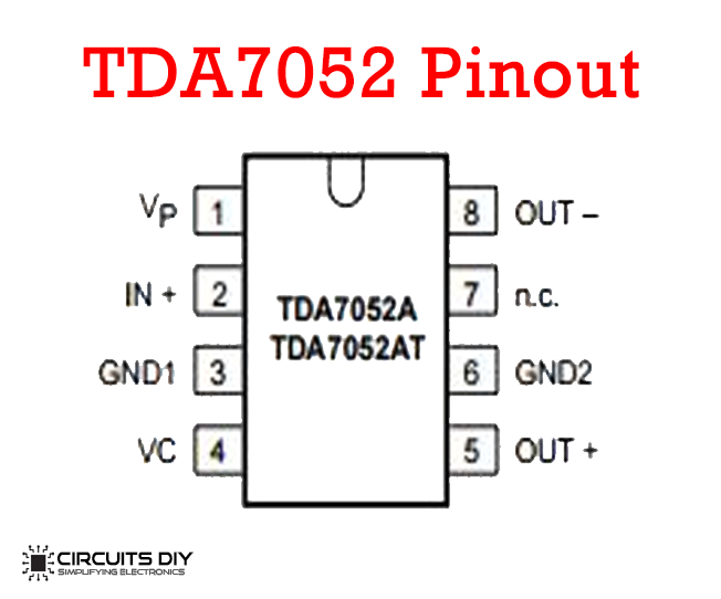
For a detailed description of pinout, dimension features, and specifications download the datasheet of TDA7052
MK484 Pinout
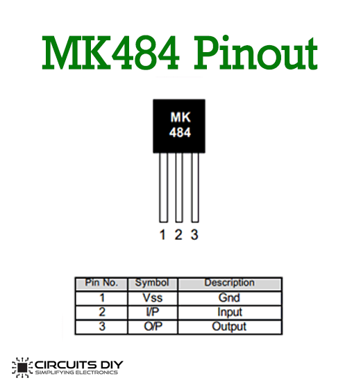
For a detailed description of pinout, dimension features, and specifications download the datasheet of MK484
AM Radio Circuit

Working Explanation
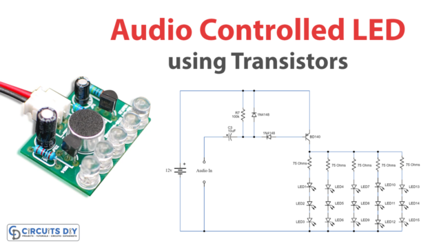
Here, in the circuit, the transistor Q1 is functioning as a preamplifier which enhances the faint sound signals of nearby or far radio stations. Then sends it to the transistor Q2 which is filling in as a small audio amplifier. The sound signal is then received by TDA7052 IC which further enhances it to drive an 8-ohm speaker. The 10K potentiometer before Q1 utilizes to alter the faint sound signals of the stations, and a 4.7K potentiometer close to the TDA7052 modify the volume.
The maximum working voltage of the MK484 AM receiver IC is 1.8 volt DC. Because of this two 1N4148 diodes utilize to step down the 9 volts originating from the battery to 1.2 volts. Moreover, the 250 Ohms variable resistor utilize to set the MK484 on the most ideal reception. Tuning to any station is quite easy with the help of 250 Ohms variable resistor. Furthermore, the inductor L1 is equivalent to 55 turns of 0.315mm enameled copper wire twisted on a 10mm x 100mm long ferrite rod. Additionally, experiment with the coil with pretty much number of turns to accomplish the best execution. You can likewise attempt other AM radio coils. For additional improving the reception, use the AM loop antenna.
Applications and Uses
- Enhances the faint audio signals of far and nearby radio stations
- An 8 ohms in-built speaker uses to produce an audible output
- The use of 250 ohms variable resistor helps in tuning any station to get good reception