The frequency-to-voltage converter converts the sinusoidal input frequency into an output voltage. In frequency to voltage converter, the basic circuit includes operational amplifiers and RC circuits. The operational amplifiers perform signal handling.
We generally use these converter circuits in places where we have to display the rotation of some device in terms of readings. For this purpose, this circuit converts frequency into voltages and gives the output. For ease of purpose, we can construct the circuit by using ICs. Also, we can alternatively use RC circuits and OP-Amps.
Hardware Components
The following components are required to make Frequency To Voltage Converter Circuit
| S.No | Component | Value | Qty |
|---|---|---|---|
| 1. | Breadboard | – | 1 |
| 2. | Electrolytic Capacitor | 100pf | 1 |
| 3. | Power Supply | 15v | 1 |
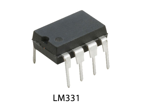
| 4. | IC | LM331 | 1 |
| 5. | Potentiometer | 5K | 1 |
| 6. | Resistors | 6.8k, 10k, 12k, 68k, 100k | 1, 2, 1, 1, 1 |
| 7. | Ceramic Capacitors | 470pf, 0.01uf | 1, 1 |
LM331 Pinout
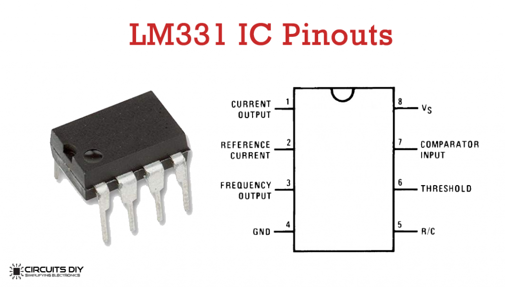
For a detailed description of pinout, dimension features, and specifications download the datasheet of LM331
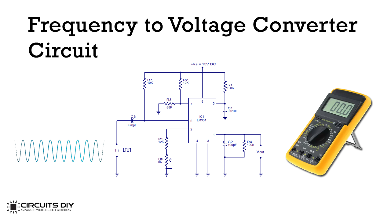
Frequency To Voltage Converter Circuit
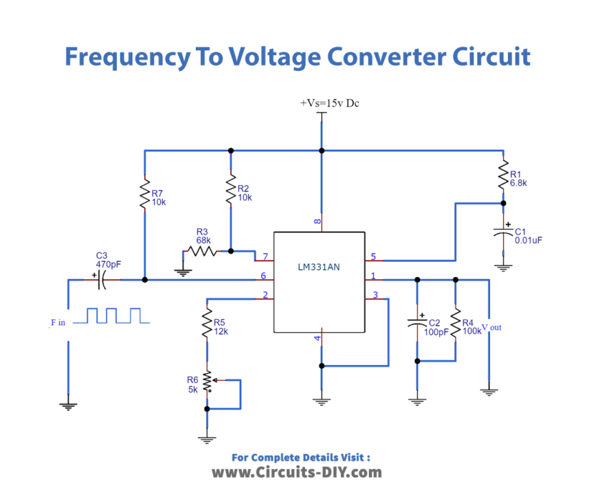
Working Explanation
Consider the circuit diagram, Here, the voltage at the output is proportional to the frequency at the input. LM331 is 8 pins IC. The source connects to pin 8 and supplies 15V. Pins 3 and 4 link to the ground. Pin 6 provides the input frequency and Pin 1 provides the output voltage. The input frequency differentiates by R7 and C3 and its resultant pulse goes to pin 6. The timer circuit triggers the built-in comparator circuit in the IC on the negative edge of the pulse.
Applications Of Frequency To Voltage Converter
Application areas include:
- Communication
- Power control
- Instrumentation and Measurement system etc.