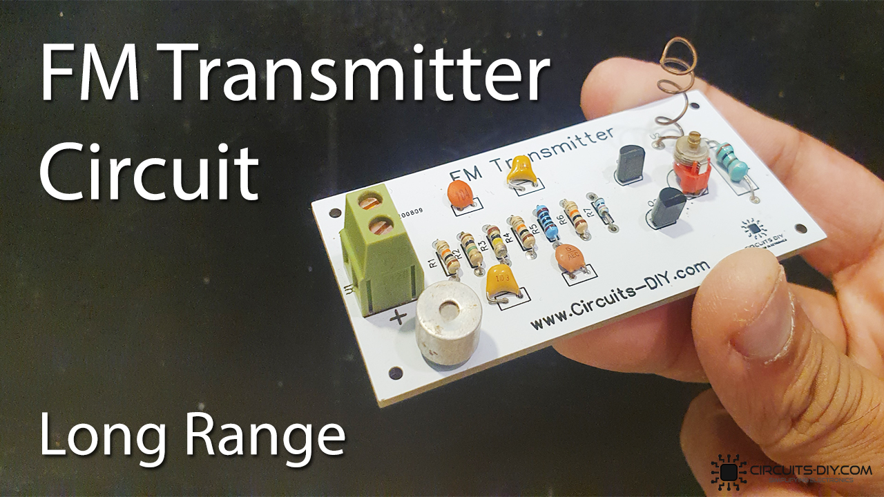
What is a High Range FM Transmitter?
An FM Transmitter is an electronic device that can air audio signals from a source on a selected range of frequencies. They are generally used to broadcast stationary audio from devices such as TV & computers, around a room. They are inexpensive & simple to design. So, in today’s article, we will look into a step-by-step tutorial on how to make a High Range FM Transmitter circuit using some NPN transistors & a small no. of other components.
Whatever may be the schematic scope or design, every FM transmitter is based on the same three key stages: Audio pre-amplification, Modulation, and, transmission. The first stage generally consists of amplifying & filtering an input audio signal. In the second stage, the input audio signal is modulated and a carrier signal is generated by a variable frequency oscillator circuit. In the last stage, the modulated audio signal is transmitted using an antenna between the FM frequency range of 88MHz to 108MHz.
PCBWay commits to meeting the needs of its customers from different industries in terms of quality, delivery, cost-effectiveness, and any other demanding requests. As one of the most experienced PCB manufacturers in China. They pride themselves to be your best business partners as well as good friends in every aspect of your PCB needs.
Hardware Components
The following components are required to make FM Transmitter Circuit
| S.no | Component | Value | Qty |
|---|---|---|---|
| 1. | FM Transmitter PCB | – | 1 |
| 2. | NPN Transistor | 2N3904 | 2 |
| 3. | Condenser mic | 5mm | 1 |
| 4. | Variable Capacitor | 40pF | 1 |
| 5. | Inductor | 0.1uH | 1 |
| 6. | Capacitor | 0.1uF, 0.01uF, 4.7pF | 3 |
| 7. | Enameled copper wire | 18 AWG | 1.5ft |
| 8. | Resistor | 1M, 100K, 10K, 1K, 100 Ohm | 7 |
| 9. | Soldering Iron | 45W – 65W | 1 |
| 10. | Soldering Wire with Flux | – | 1 |
| 11. | DC Battery | 9V | 1 |
| 12. | Battery Clips | – | 1 |
| 13. | Jumper Wires | – | As per need |
2N3904 Pinout
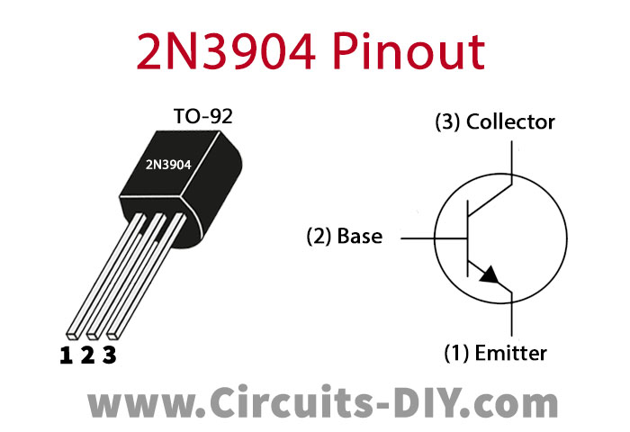
For a detailed description of pinout, dimension features, and specifications download the datasheet of 2N3904
FM Transmitter Circuit
Working Explanation
The working of this circuit is pretty simple, an input audio signal from a device such as a smartphone is taken through an electret mic. Here, a coupling capacitor of 0.1uF is used to block the DC component of the signal, allowing only AC to flow. This signal acts as a control signal to the base of the 2n3904 transistor (Q1).
The amplified collector output is then sent to the base of the Q2 transistor. The power of the collector output is then modulated & tuned using a trimmer capacitor & is then adjusted to the frequency range of the FM receiver circuit using an LC combination, which is then broadcasted using an 18 AWG coiled antenna.
Applications
- Used for commercial broadcast band transmitters.
- It is also used in processes such as music synthesis & live media production & recording.
Related posts:
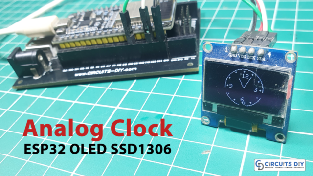 Analog Clock using ESP32 & SSD1306 OLED Display
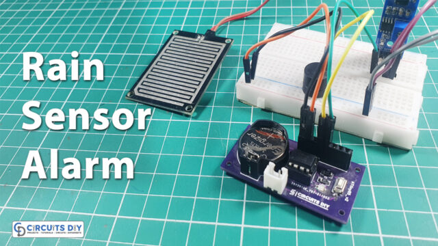 Rain Detection Alarm System using AtTiny85 - Rain Sensor
 Copper Clad Laminate (CCL) | Comprehensive Guide For Beginners
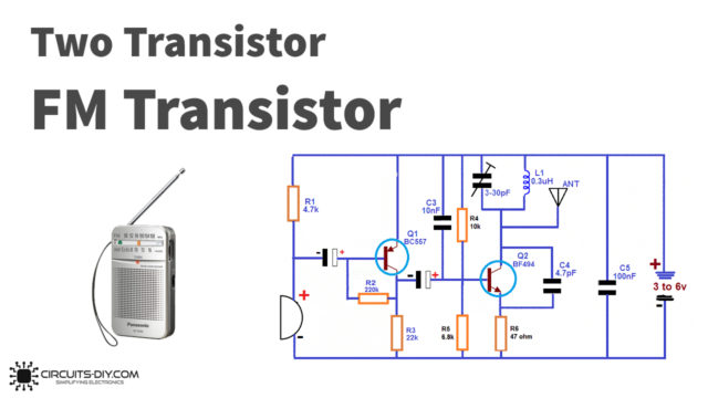 Two Transistors FM Transmitter
 Black Printed Circuit Board | Design Benefits And Limitations
 Home Automation with ESP8266 Web Server & Relay Module