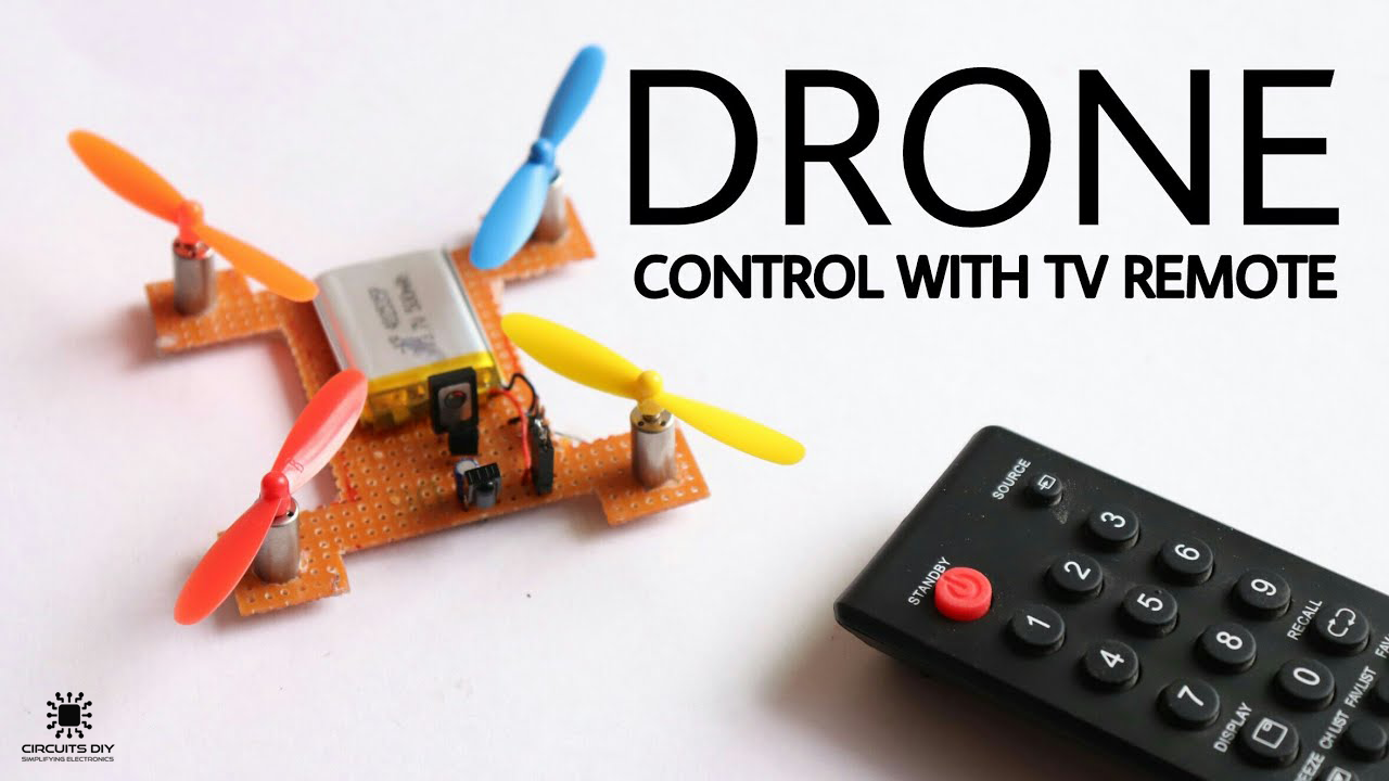
A Drone or in more technical terms unmanned aerial vehicles (UAVs) or unmanned aircraft systems (UASs) are an integral part of today’s various businesses and governmental organizations and have managed to pierce through areas where certain industries were either stagnant or lagging behind. So, in this project, we will go through a step by procedure on How to make a basic drone using a small number of components.
An electronic drone or a UAV is essentially a flying robot that can be remotely controlled or fly autonomously through software-controlled flight plans in their embedded systems, working in conjunction with onboard sensors and GPS.
JLCPCB is the foremost PCB prototype & manufacturing company in china, providing us with the best service we have ever experienced regarding (Quality, Price Service & Time).
Hardware Components
You will need the following parts to build this project.
| S.no | Component | Value | Qty |
|---|---|---|---|
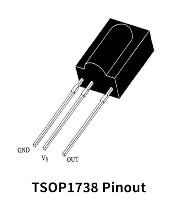
| 1. | IR Receiver | TSOP1738 | 1 |
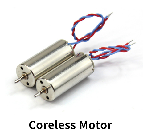
| 2. | Coreless DC Motor | 27mA/44300rpm/3.7V | 4 |
| 3. | Super Glue | – | 1 |
| 4. | PNP Transistor | BC557, BD140 | 2 |
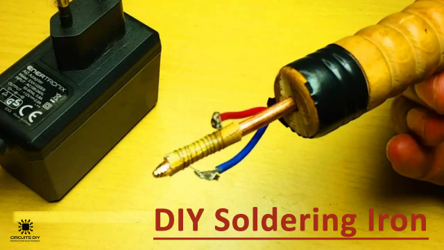
| 5. | Soldering Iron | 45W – 65W | 1 |
| 6. | Capacitor | 22uF/16V | 1 |
| 7. | Soldering wire & flux | – | 1 |
| 8. | Li-ion Battery | 3.7V/500mAh | 1 |
| 9. | Headers | Male | 4 |
| 10. | Propeller Fan Blades | 3″ | 4 |
| 11. | Filer | – | 1 |
| 12. | DC hand drill with drill bits | – | 1 |
| 13. | Veroboard | – | 1 |
| 14. | Connecting Wires | – | As per need |
| 15. | TV remote | – | 1 |
Coreless DC Motor
TSOP1738 Pinout
Useful Steps For Making a Drone
The following are the steps on ‘How To make a drone’
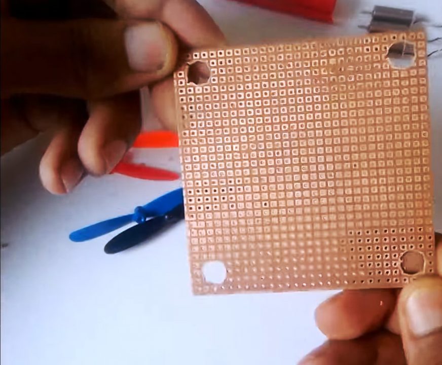
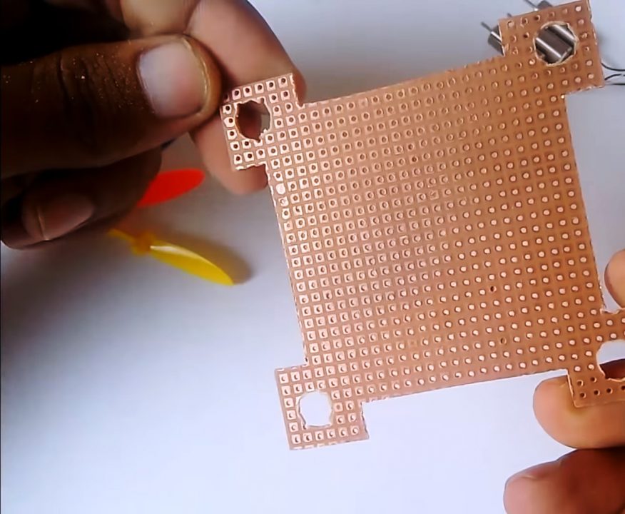
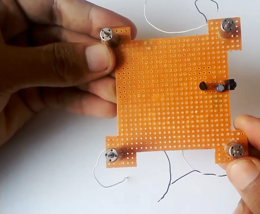
1) Drill & file down holes on the 4 corner of the Vero board, after this mark & cut the initial layout for your drone.
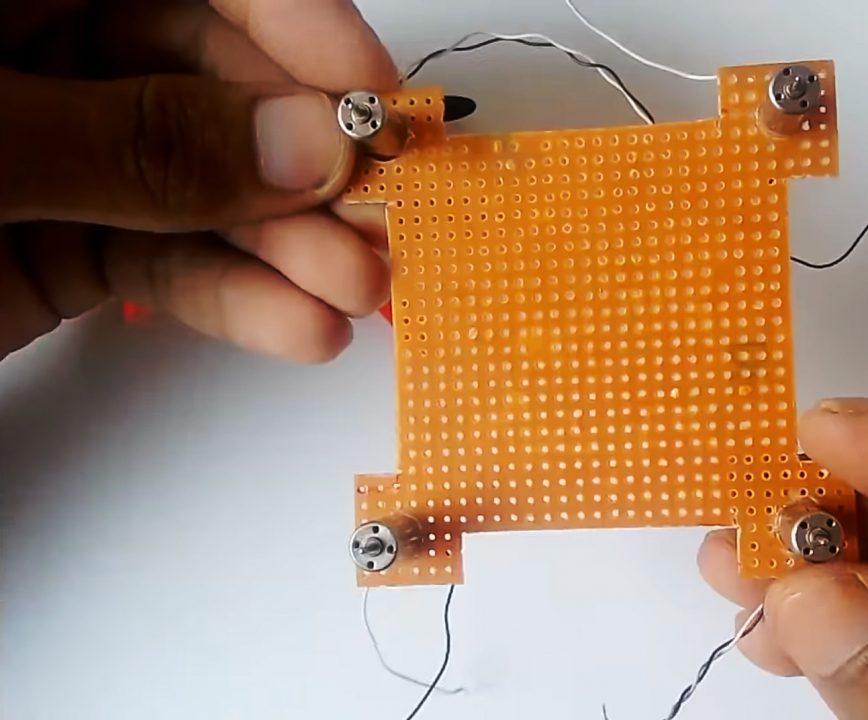
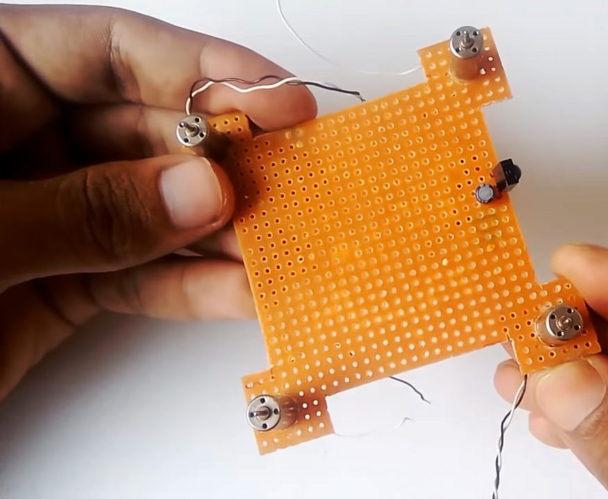
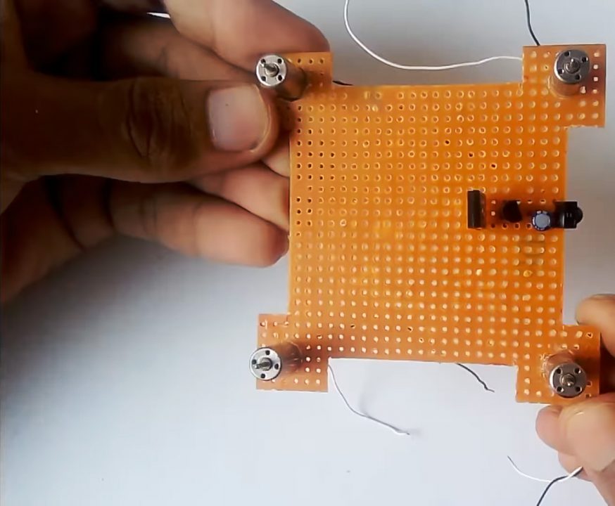
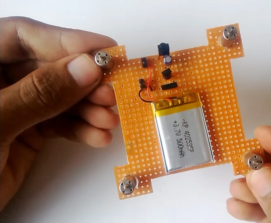
2) Set the 4 coreless DC motors in their respective positions using super glue.
3) Solder the IR sensor. After this, Solder the +ve terminal of the capacitor to the output of the IR sensor & the -ve terminal to GND.
4) Solder the base of the BC557 transistor to the output of the IR sensor & the emitter to Vcc.
5) Solder the base of the BD140 transistor to the collector of BC557 & the emitter to the IR sensor.
4) Solder the +ve terminal of all 4 motors to Vcc & the -ve terminal to the collector of BD140.
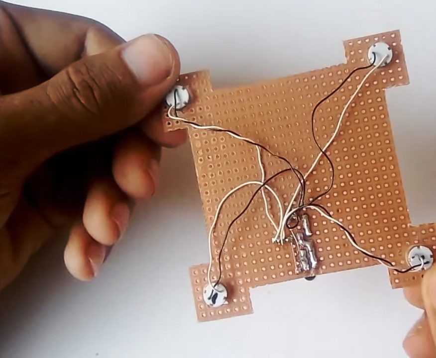
5) Connect a 3.7V Li-ion Battery to the Vcc & GND of the drone circuit.
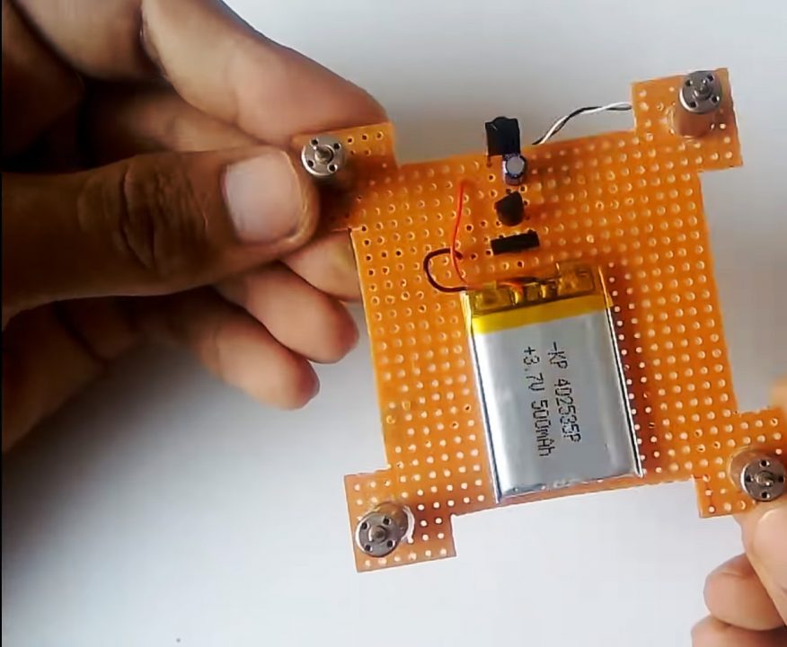
6) Attach headers for powering up the circuit & charging the battery.
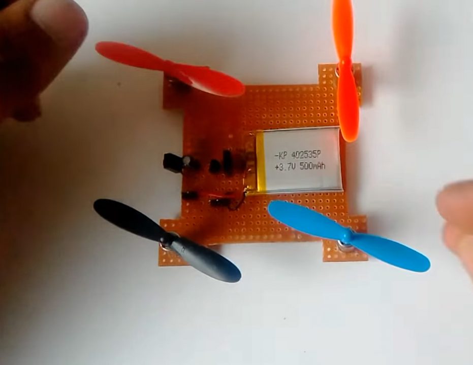
7) Now attach all propeller blades to the motor shaft.
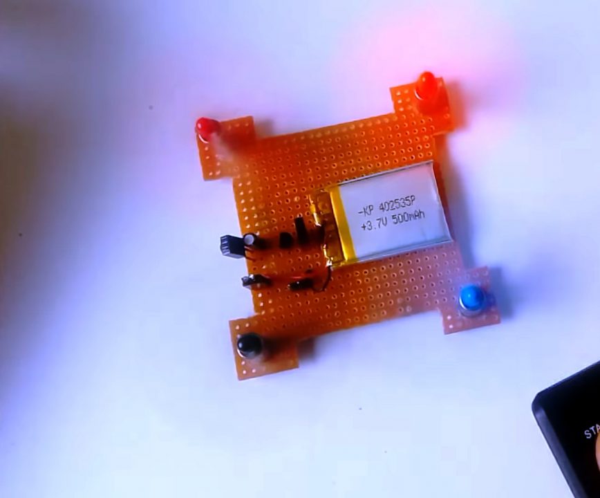
8) Test the circuit, make weight adjustments where necessary.
Working Explanation
The working of this circuit is pretty simple. On receiving an IR signal from a device such as a TV remote. The IR sensor sends a control signal to the base of the BC557 PNP transistor. A 22uF capacitor filters out any residual noise that might be occurring from the IR receiver. The collector output from transistor Q1 acts as control signal to the base of the BD140 transistor.
The collector output simultaneously triggers the power of all 4 DC motors, prompting them to spin at equal time & RPM.
Applications of Drones
- Drones are used for purposes such as to spot wildfires & track their movement.
- Drones can also survey landscapes with thousands of images that can be stitched together into 3D maps.
- They can also be used by law enforcement agencies for surveillance purposes.