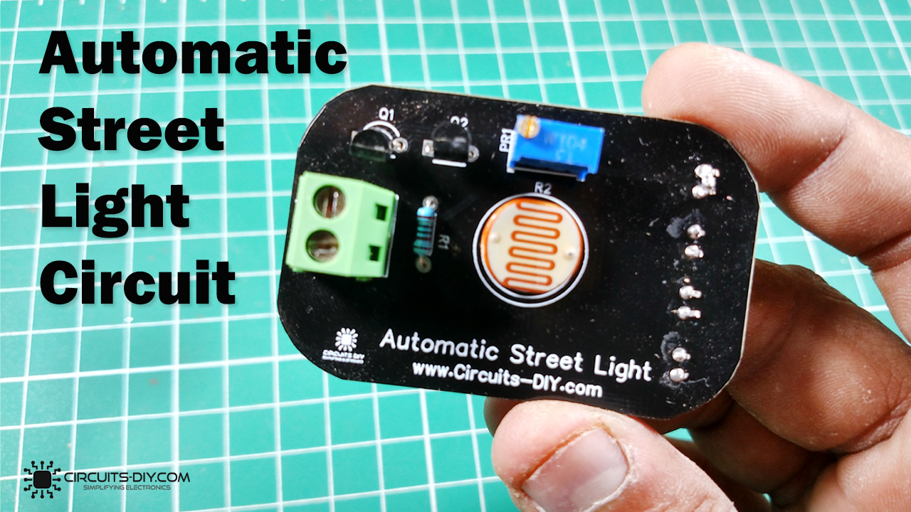
An Automatic street night light, as the name suggests, is an electronic street light that switches itself ON & OFF without the need for any human intervention. It senses the intensity of light from its immediate surroundings & determines whether it’s day or night. This project finds its applications in places such as streets, gardens, and other public places. So, in today’s tutorial, we will go over a step-by-step process of designing an Automatic Street Night Light Circuit Using an LDR (light-dependent resistor).
The main component of this automatic street light is an LDR or a light-dependent resistor. LDRs are electronic components that are sensitive to light intensity. Its behavior is similar to a photocell that works on the principle of photoconductivity. This passive component is basically a resistor whose resistance value decreases when the intensity of light increases. It is not uncommon for the values of resistance of an LDR or photoresistor to be at several MΩ in darkness and then to fall to a few hundred ohms in bright light.
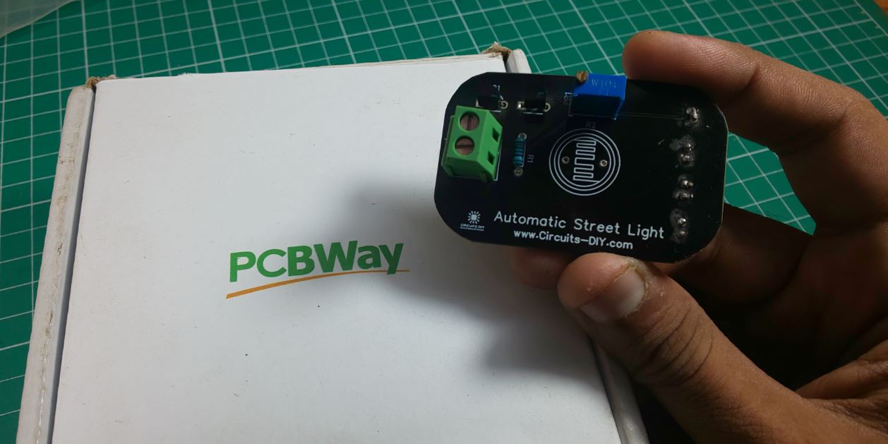
PCBWay commits to meeting the needs of its customers from different industries in terms of quality, delivery, cost-effectiveness, and any other demanding requests. As one of the most experienced PCB manufacturers in China. They pride themselves to be your best business partners as well as good friends in every aspect of your PCB needs.
Hardware Components
The following components are required to make an Automatic Street Light Circuit
| S.no | Component | Value | Qty |
|---|---|---|---|
| 1. | LDR | 5mm | 1 |
| 2. | Automatic street light PCB | PCBWay | 1 |
| 3. | NPN transistor | BC547 | 2 |
| 4. | LED | 5mm/3.5V | 3 |
| 5. | Resistor | 1K, 100K Var | 2 |
| 6. | Soldering Iron | 45W – 65W | 1 |
| 7. | Soldering wire with flux | – | 1 |
| 8. | DC Battery | 12V | 1 |
| 9. | Battery Clip | – | 1 |
| 10. | Soldering Stand | – | 1 |
| 11. | Jumper Wires | – | As per need |
BC547 Pinout

For a detailed description of pinout, dimension features, and specifications download the datasheet of BC547
Automatic Street Light Circuit
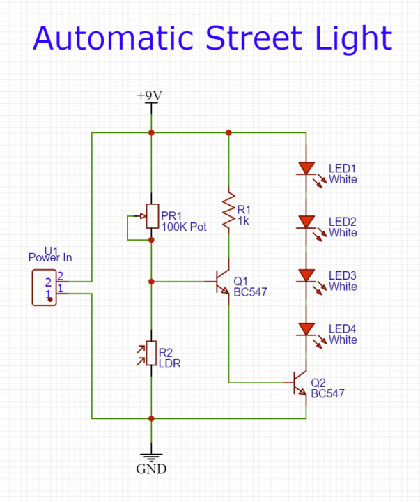
Working Explanation
This circuit powers an array of three LEDs when the intensity of the light on the LDR decreases. During the daytime, the light intensity on the LDR increases, decreasing the resistance value of the LDR. This diminishes the strength of the control signal on the base of transistor Q1 & the LEDs remain off.
As the night falls the light intensity over the LDR decreases, subsequently increasing the resistance of the LDR. This allows the control signal to flow to the base of the BC547 transistor. The output from Q1 acts as a control signal for the base terminal of the transistor Q2. The collector output from transistor Q2 then triggers the LED array to glow.
Applications
- Usually used as an energy-efficient solution to light up areas such as roads, highways & motorways.
- Serves as an emergency backup in security systems and industrial sites.
- It can function as an emergency lamp in home & office setups.
- It can be used in study rooms and workplaces in order to avoid sudden power failures.