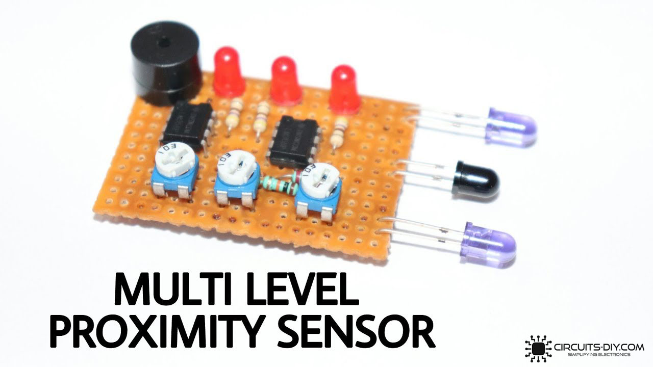
Today in this article we’ll make a simple Multi-Level Proximity Sensor using the operational amplifier IC LM358. You can use this circuit for detecting obstacles in front of an IR Infrared LED. This circuit is very simple and easy to make just follow the step-by-step instructions mentioned below
Multi Level Proximity Sensor?
Multi-level Proximity sensors are a type of proximity sensor that detects the movement/presence of objects without physical contact and relays that information captured into an electrical signal. Infrared proximity sensors have high operational life due to the absence of mechanical parts. So, in today’s tutorial, we will go over a step-by-step procedure on how to Make a Multi-Level Proximity Sensor Using the LM358 Op-Amp IC.
The main component of this circuit is an LM358 IC. LM358 is a dual op-amp IC integrated with two op-amps powered by a common power supply. It can be considered as one-half of the LM324 Quad op-amp which contains four op-amps with a common power supply.
JLCPCB is the foremost PCB prototype & manufacturing company in china, providing us with the best service we have ever experienced regarding (Quality, Price Service & Time).
Hardware Component
The following components are required to make Proximity Sensor Project
| S.no | Component | Value | Qty |
|---|---|---|---|
| 1. | Op-Amp IC | LM358 | 2 |
| 2. | IR LED | 3.5mm | 2 |
| 3. | Photodiode | – | 1 |
| 4. | Potentiometer | 10K | 3 |
| 5. | Resistors | 10K, 220 Ohm, 470 Ohm | 5 |
| 6. | Buzzer | 9V | 1 |
| 7. | LED | 5mm, 3.5V | 3 |
| 8. | Soldering Iron | 45W – 65W | 1 |
| 9. | Soldering Wire with Flux | – | 1 |
| 10. | Veroboard | – | 1 |
| 11. | DC Battery | 9V | 1 |
| 12. | Battery Clip | – | 1 |
| 13. | Jumper Wires | – | As per need |
LM358 Pinout

For a detailed description of pinout, dimension features, and specifications download the datasheet of LM358
Useful Steps
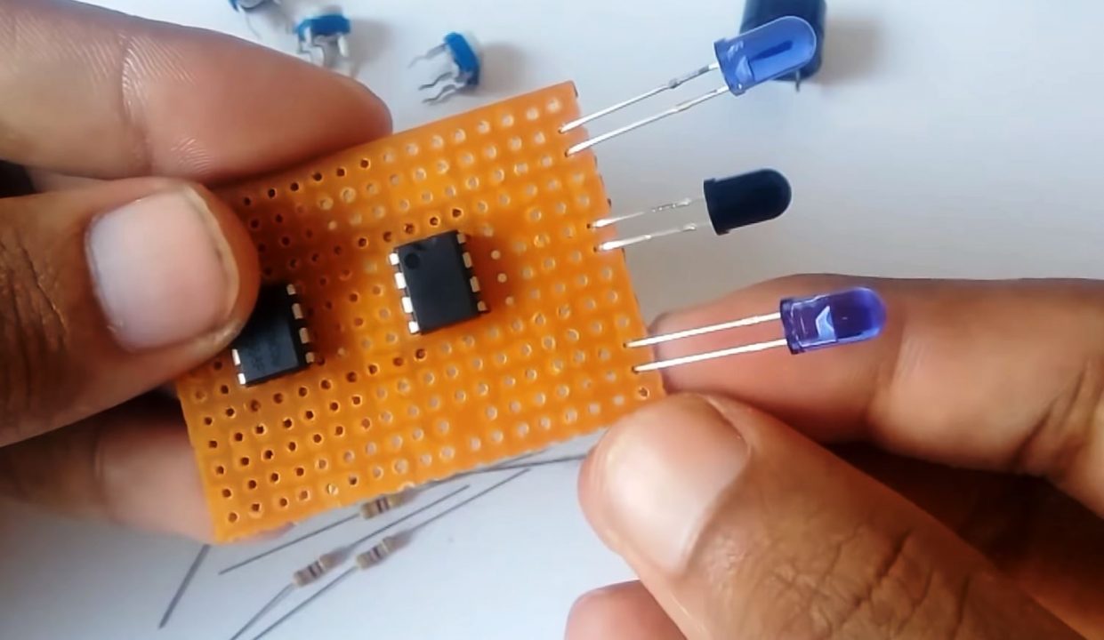
1) Solder the LM358 Op-Amp on the Veroboard. after that, solder the IR LEDs & receiver (photodiode) on the Veroboard.
2) Solder a 220 Ohm resistor between pin 4 of the LM358 IC & the -ve terminal of the photodiode.
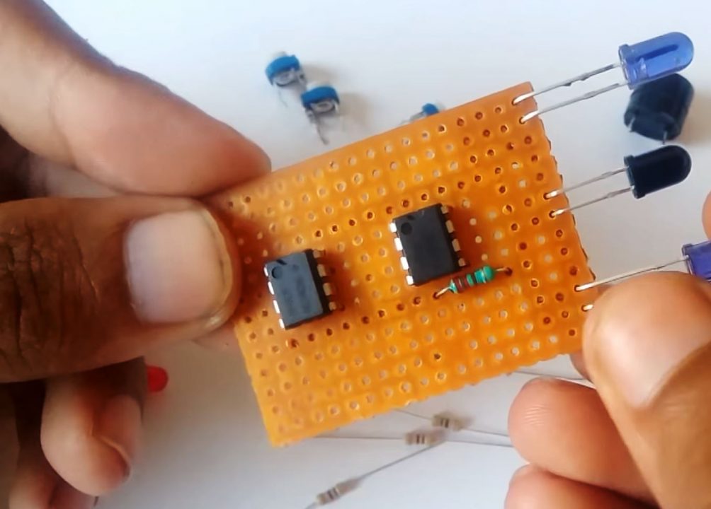
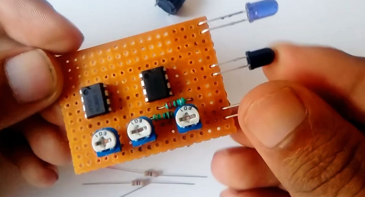
3) Now solder the 10K resistor between pin 4 & pin 5 of the IC. After that, solder the 10K preset pots on the Veroboard.
4) After that, solder the LEDs on the Veroboard.

5) Solder the 470 Ohm resistors between pins 1 & 7 of the IC and the +ve terminal of the LED.
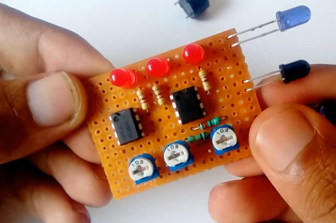
6) Solder the buzzer between pins 4 & 7 of the IC.

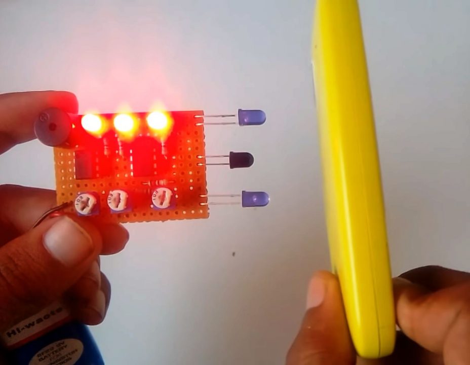
7) Power up & test the circuit.
Working Explanation
The working of this circuit can be broken down into two separate stages, the IR transceiver stage & the amplification stage. In the first stage, the rays emitted from either one of the IR LEDs are bounced back and received on the photodiode. With respect to the distance of the object from the proximity sensor & the LED from which the IR transmission is received, either Op-Amp IC (LM358) 1 or 2 will go in amplification mode.
In the second stage, The LM358 Op-Amp IC receives the noninverting input from either one of the IR pairs & signals an amplified output on one of the three available output LEDs.
Applications
- Generally used in home security appliances such as motion sensors & security alarms to keep your home safe from intruders & burglars.
Related posts:
 TV Remote Control Jammer Circuit - Electronics Projects
 Matrix Scrolling Weather Station & Clock
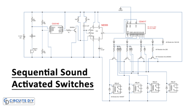 Sequential Sound Activated Switches - Electronics Project
 Heart Rate Monitor Circuit Using LM358 IC | DIY Project
 DIY 12 Volt Soldering Iron - Homemade
 Getting Started with ESP32 CAM & Video Streaming Over WiFi


2 thoughts on “How To Make a Multi-Level Proximity Sensor Using LM358 Op-Amp IC”
Comments are closed.