To understand electronic appliances, nearly all types of sensors and transducers transform actual parameters such as light, temperature, weight, etc., into voltage values. Therefore, the variations in the voltage level will allow us to determine the digital parameters. This variance is minimal (low-level signals) for specific applications, such as biosensors, and it is essential to keep records of even the minute variation to get accurate results. Thus, an Instrumentation Amplification is used for these purposes.
In addition to standard op-amps IC, there are certain unique amplifier types such as INA114 IC for instrument amplifiers. They just seem like a few standard op-amps adapted to particular applications.
An instrument amplifier increases the voltage variation and produces a differential output like all other op-amps. Besides a regular amplifier, the instrumentation amplifiers are exceptionally gainful with high input impedance, thus having maximum differential inputs for typical mode noise rejection. This article will learn how to build an Instrumentation amplifier and how to use it for our applications as a standard Op-amp, as the in-amp ICs are costlier than Op-amps.
Hardware Components
The following components are required to make the Instrumentation Amplifier Circuit
| S.no | Component | Value | Qty |
|---|---|---|---|
| 1. | Op-amp IC | LM358 | 3 |
| 2. | Resistor | 10k, 22k | 6,1 |
| 3. | Input Power Supply | 3.3V | 1 |
| 4. | Input Power Supply | 2.8V | 1 |
| 5. | Input Power Supply | 5V | 1 |
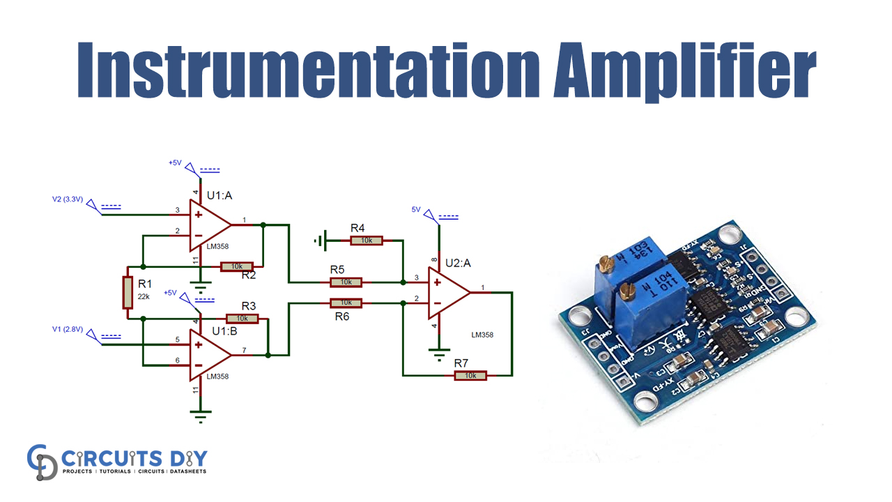
LM358 Pinout

For a detailed description of pinout, dimension features, and specifications download the datasheet of LM358
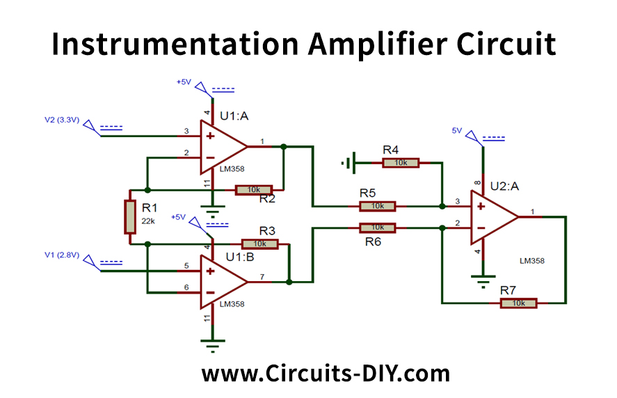
Instrumentation Amplifier Circuit
Working Explanation
The circuit needs three op-amps; I use 2 LM358 ICs. The LM358 is the double op-amp module of two op-amps, so we need two op-amps for our circuit. However, you can utilize three single-package op-amp LM741 and one LM324 op-amp quad-package.
The U1:A & U1:B op-amps are used on the above circuit as a voltage buffer to ensure that the output impedances are high. The U2:A op-amp functions as an op-amp. Since all the difference op-amp resistors are 10 k, it works as the differential amplifier of unity gain which means that the output voltage is the difference in voltage of pin 3 to pin 2 of U2:A.
The output voltage can be measured using the following formulas of the instrumentation amplifier circuit.
Vout = (V2-V1)(1+(2R/Rg))
Where R = Circuit resistor. R = R2 = R3=R4 = 10k R5 = R6 = R7
Rg = resistance gain. Rg = R1; that’s 22k here.
The R and Rg values determine the amplifier’s gain. The benefit value can be defined by
Gain = (1+(2R/Rg))
The voltages V1 are 2.8V and V2 3.3V, as you can see. R is 10k, and Rg is 22k. The value is 10k. In the above formulae, put all those values.
Vout = (V2-V1)(1+(2R/Rg))
(3.3-2.8)(1+(2×10/22))
(0.5)*(1.9)
= 0.95V
We have a value of 0.95V, which corresponds to the above approximation. The voltage differential of the circuit, as mentioned above, is therefore 1.9. This circuit tests the difference between the voltages of input and multiplies the gain as the output voltage.
Applications and Uses
It uses an amplifying instrument’s output voltage gain.