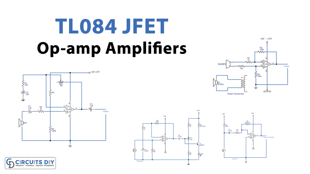
The TL084 is a high-speed J-FET input quad operational amplifier in a monolithic integrated circuit that incorporates well-matched, high-voltage J-FET and bipolar transistors. High slew rates, low input bias and offset currents, and a low offset voltage temperature coefficient characterize the device. In general, the TL084 op-amp is employed in audio systems because it’s a low-noise operational amplifier that really is inexpensive. In this article, we are going to discuss 3 “TL084 JFET Op-amp Circuits”.
Features of TL084 IC
The minimum operating voltage is 7V
Input bias current is 20pA
The input offset voltage is 3mV
CMRR or common-mode rejection ratio is 86dB
The gain is 200 V/mV
Bandwidth is 4MHz
The typical range of operating voltage is +18V to -18V
Protection from output short circuit
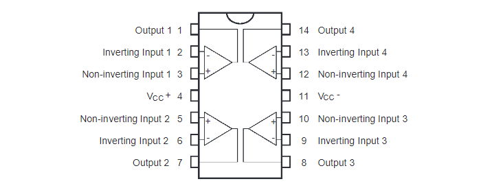
Pin Configuration
Pin No
Pin Name/Description
1
Output pin
2
Inverting input pin
3
Input non-inverting pin
4
Positive supply rail (Vcc)
5
Non-inverting input pin
6
Inverting input pin
7
Output pin
8
Output pin
9
Inverting input
10
Non-inverting input
11
Negative supply rail (Vcc)
12
Non-inverting input
13
Inverting input
14
Output
Output Pins: These pins are the four op-amp’s output pins
Input Inverting Pins: These pins are the four Op-Amps input inverting pins
Input Non-Inverting Pins: These pins are the four Op-Amps input non-inverting pins
Vcc (+): This is the Op-Amp’s positive supply rail
Vcc (-): This is the Op-Amp’s negative supply rail
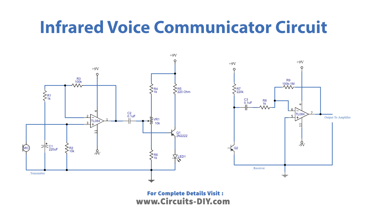
There are two sections of this infrared voice communicator circuit. There is a transmitter to convert a speech to a signal. For this, we employ the Dynamic microphone preamplifier. Then, using the Q1 transistor, we drive a stronger signal to the infrared LED, to convert the signal into infrared light. We adjust the potentiometer VR1 to modify the quality of the sound or the current to LED1. resistor R5 restricts the maximum current to 40mA. The phototransistor converts an infrared light signal to an audio signal as the receiver. The signal is then amplified by IC1/2 to a greater level than the power amplifier’s input.
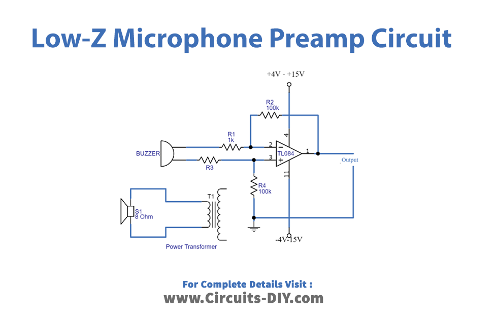
2. Low-Z Microphone Preamplifier Circuit
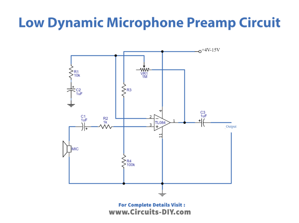
3. Low Dynamic Microphone Preamplifier Circuit
Application Uses of TL084 IC
This op-amp is utilized in circuits that require a high input impedance.