A remote control circuit allows the operation of devices that are out of convenient reach for direct operation of controls. It is an electronic device used to operate another device from a distance, usually wirelessly. They function best only when used from a short distance. Here IR beam from the remote control travels a very short distance with a narrow-angle. Therefore we design an IR remote control extender circuit with few components. This circuit is used to relay signals from an Infra-Red remote control in one room to an IR-controlled appliance in another room. For example, if you have a bedroom TV set that is wired to the video or satellite in another room, then you can change channels on the remote satellite receiver using this circuit.
Hardware Required
| S.no | Component | Value | Qty |
|---|---|---|---|
| 1. | Transistor | BC109C | 1 |
| 2. | IR Receiver | TSOP1736 | 1 |
| 3. | IC | 4049 | 1 |
| 4. | Resistor | 3.3KΩ,10KΩ,1KΩ,33Ω | 1,1,1,1 |
| 5. | Capacitor | 0.1uF | 2 |
| 6. | LED | – | 2 |
| 7. | Connecting Wires | – | – |
| 8. | Battery | 9V | 1 |
Circuit Diagram
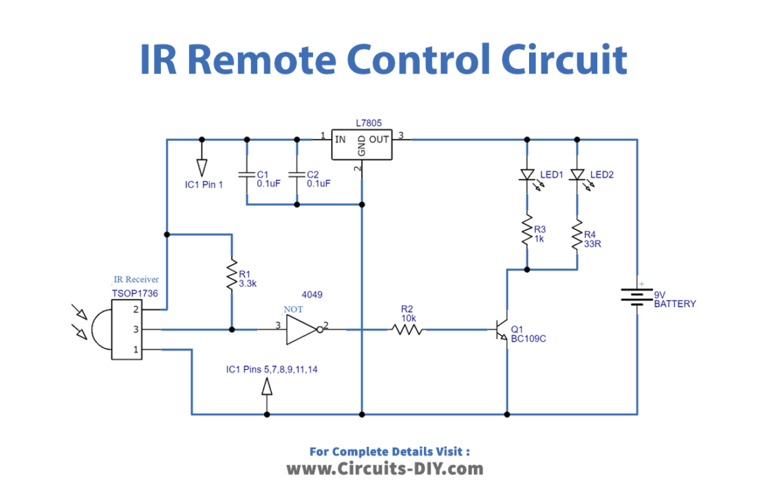
Construction and Working
As we can see, the main part of the circuit is the IR receiver TSOP 1736. This IR receiver is used to detect the IR beam from the remote control. Here output from this sensor is fed to not gate and then this inverted output is connected to the transistor Q1 base. This NPN transistor acts as a switch and the IR LEDs connected with this transistor create an IR beam as received. This circuit will only receive signals from remote controls which use a 36 kHz carrier but rebroadcasts them as carrier-free data signals, which will not operate the targeted consumer equipment. Because it is designed to receive the carrier signal and reject anything else as interference.
Applications
Used to turn on or off electronic devices like TVs, radios, and washing machines.