Introduction
The Dual Axis XY Arduino joystick module-controlled SG51R servo motors system is a versatile and precise solution for controlling the movement of two SG51R servo motors. The system utilizes an Arduino UNO microcontroller to interface with a Dual Axis XY joystick module, which allows for intuitive and precise control of the servo motors’ rotation. The joystick module generates an analog voltage in response to the user’s input, which the Arduino maps to specific angles of rotation for each servo motor.
A Dual Axis XY Arduino joystick module is a type of input device that can be used to control electronic devices such as robots, drones, or other automated systems. It typically contains two joystick potentiometers, one for the X-axis and one for the Y-axis, which can be moved in different directions to generate an analog voltage. The voltage generated by the joystick can be read by an Arduino microcontroller, which can then be used to control the movement of motors or other devices.
Hardware Components.
You will require the following hardware for Interfacing Joystick Servo Motor with Arduino.
| S.no | Component | Value | Qty |
|---|---|---|---|
| 1. | Arduino UNO | – | 1 |
| 2. | USB Cable Type A to B | – | 1 |
| 3. | Joystick | – | 1 |
| 4. | Servo Motor | – | 1 |
| 5. | Pan-tilt kit with servo motor | – | 1 |
| 6. | Power Adapter for Arduino | 9V | 1 |
| 7. | Jumper Wires | – | 1 |
Joystick Servo Motor with Arduino
- Connect the X-axis of the joystick to analog pin A0 and the Y-axis to analog pin A1 of the Arduino. Connect the two servo motors to digital pins 9 and 10.
- In the Arduino IDE, include the Servo library at the beginning of the sketch:
#include <Servo.h>
- Declare the Servo objects and variables for storing the joystick values:
Servo servo1, servo2;
int xVal, yVal;
- In the setup() function, attach the servos to their corresponding pins and initialize the serial communication:
servo1.attach(9);
servo2.attach(10);
Serial.begin(9600);
- In the loop() function, read the values from the joystick and use the map() function to scale them to the range of the servo’s motion:
xVal = analogRead(A0);
yVal = analogRead(A1);
xVal = map(xVal, 0, 1023, 0, 180);
yVal = map(yVal, 0, 1023, 0, 180);
- Use the servo objects to set the position of the motors based on the joystick values:
servo1.write(xVal);
servo2.write(yVal);
- Send the joystick and servo position values to the serial monitor:
Serial.print("X-axis: ");
Serial.print(xVal);
Serial.print(" Y-axis: ");
Serial.println(yVal);
- Finally, include a delay to avoid overloading the servos:
delay(15);Schematic
Make connections according to the circuit diagram given below.
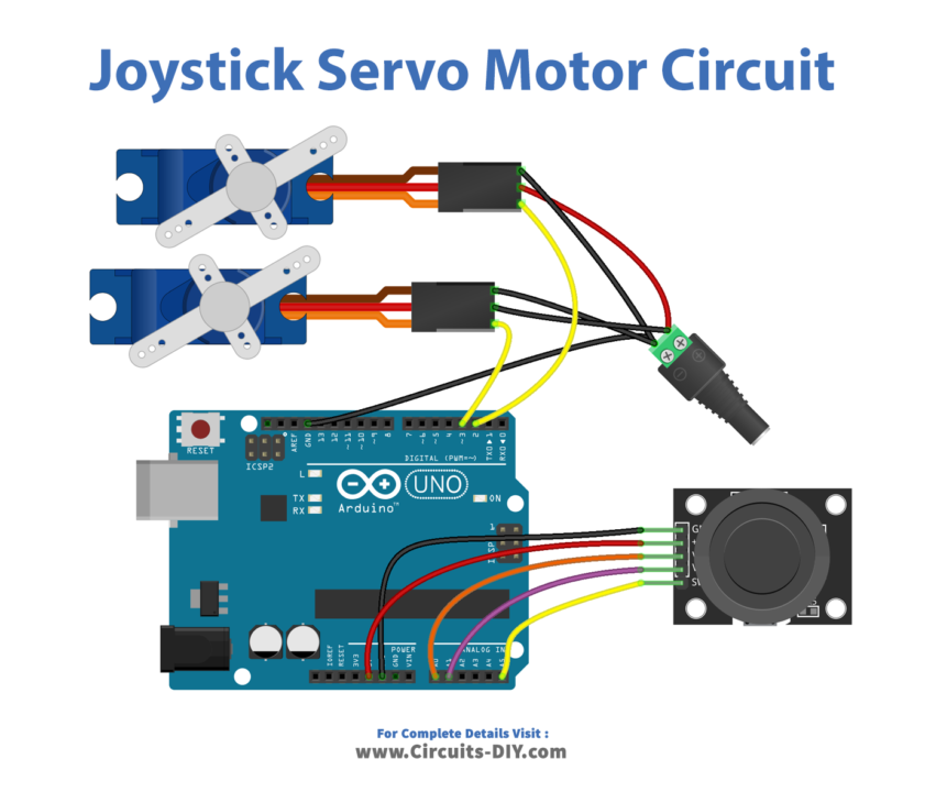
Wiring / Connections
| Arduino | Joystick | Servo |
|---|---|---|
| 5V | 5V | VCC |
| GND | GND | GND |
| A0 | VRX | |
| A1 | VRY | |
| A5 | SW | |
| D2 | Yellow | |
| D3 | Blue |
Installing Arduino IDE
First, you need to install Arduino IDE Software from its official website Arduino. Here is a simple step-by-step guide on “How to install Arduino IDE“.
Installing Libraries
Before you start uploading a code, download and unzip the following libraries at /Progam Files(x86)/Arduino/Libraries (default), in order to use the sensor with the Arduino board. Here is a simple step-by-step guide on “How to Add Libraries in Arduino IDE“.
Code
Now copy the following code and upload it to Arduino IDE Software.
Arduino Code – The servo motors rotate according to the movement of the joystick’s thump
#include <Servo.h>

#define VRX_PIN      A0 // Arduino pin connected to VRX pin
#define VRY_PIN      A1 // Arduino pin connected to VRY pin
#define SERVO_X_PIN  2  // Arduino pin connected to Servo motor 1
#define SERVO_Y_PIN  3  // Arduino pin connected to Servo motor 2

Servo xServo;  // create servo object to control a servo 1
Servo yServo;  // create servo object to control a servo 2

void setup() {
  Serial.begin(9600) ;
  xServo.attach(SERVO_X_PIN);
  yServo.attach(SERVO_Y_PIN);
}

void loop() {
  // read analog X and Y analog values
  int xValue = analogRead(VRX_PIN);
  int yValue = analogRead(VRY_PIN);

  int xAngle = map(xValue, 0, 1023, 0, 180); // scale it to the servo's angle (0 to 180)
  int yAngle = map(yValue, 0, 1023, 0, 180); // scale it to the servo's angle (0 to 180)

  xServo.write(xAngle); // rotate servo motor 1
  yServo.write(yAngle); // rotate servo motor 2

  // print data to Serial Monitor on Arduino IDE
  Serial.print("Joystick: ");
  Serial.print(xValue);
  Serial.print(", ");
  Serial.print(yValue);
  Serial.print(" => Servo Motor: ");
  Serial.print(xAngle);
  Serial.print("°, ");
  Serial.print(yAngle);
  Serial.println("°");
}
Arduino Code – Use the joystick to command servo motors
#include <Servo.h>
#include <ezButton.h>

#define VRX_PIN      A0 // Arduino pin connected to VRX pin
#define VRY_PIN      A1 // Arduino pin connected to VRY pin
#define SW_PIN   2  // Arduino pin connected to SW  pin
#define SERVO_X_PIN  2  // Arduino pin connected to Servo motor 1
#define SERVO_Y_PIN  3  // Arduino pin connected to Servo motor 2

#define COMMAND_NO     0x00
#define COMMAND_LEFT   0x01
#define COMMAND_RIGHT  0x02
#define COMMAND_UP     0x04
#define COMMAND_DOWN   0x08

#define LEFT_THRESHOLD  400
#define RIGHT_THRESHOLD 800
#define UP_THRESHOLD    400
#define DOWN_THRESHOLD  800

#define UPDATE_INTERVAL 100 // 100ms

ezButton button(SW_PIN);
Servo xServo;  // create servo object to control a servo 1
Servo yServo;  // create servo object to control a servo 2

int xValue = 0 ; // To store value of the X axis
int yValue = 0 ; // To store value of the Y axis
int xAngle = 90; // the center position of servo #1
int yAngle = 90; // the center position of servo #2
int command = COMMAND_NO;

unsigned long lastUpdateTime = 0;

void setup() {
  Serial.begin(9600) ;

  xServo.attach(SERVO_X_PIN);
  yServo.attach(SERVO_Y_PIN);

  button.setDebounceTime(50); // set debounce time to 50 milliseconds
}

void loop() {
  button.loop(); // MUST call the loop() function first

  if (millis() - lastUpdateTime > UPDATE_INTERVAL) {
    lastUpdateTime = millis() ;

    // read analog X and Y analog values
    xValue = analogRead(VRX_PIN);
    yValue = analogRead(VRY_PIN);

    // converts the analog value to commands
    // reset commands
    command = COMMAND_NO;

    // check left/right commands
    if (xValue < LEFT_THRESHOLD)
      command = command | COMMAND_LEFT;
    else if (xValue > RIGHT_THRESHOLD)
      command = command | COMMAND_RIGHT;

    // check up/down commands
    if (yValue < UP_THRESHOLD)
      command = command | COMMAND_UP;
    else if (yValue > DOWN_THRESHOLD)
      command = command | COMMAND_DOWN;

    // NOTE: AT A TIME, THERE MAY BE NO COMMAND, ONE COMMAND OR TWO COMMANDS

    // print command to serial and process command
    if (command & COMMAND_LEFT) {
      Serial.println("COMMAND LEFT");
      xAngle--;
    }

    if (command & COMMAND_RIGHT) {
      Serial.println("COMMAND RIGHT");
      xAngle++;
    }

    if (command & COMMAND_UP) {
      Serial.println("COMMAND UP");
      yAngle--;
    }

    if (command & COMMAND_DOWN) {
      Serial.println("COMMAND DOWN");
      yAngle++;
    }
  }

  if (button.isPressed()) {
    Serial.println("The button is pressed");
    xAngle = 90; // the center position of servo #1
    yAngle = 90; // the center position of servo #2
  }

  xServo.write(xAngle); // rotate servo motor 1
  yServo.write(yAngle); // rotate servo motor 2

  // print data to Serial Monitor on Arduino IDE
  Serial.print("Servo Motor's Angle: ");
  Serial.print(xAngle);
  Serial.print("°, ");
  Serial.print(xAngle);
Serial.println("°");
}
Working Explanation
The Arduino sketch starts by including the Servo library at the beginning of the sketch and declaring the Servo objects and variables for storing the joystick values. The servo objects are attached to their corresponding digital pins. The setup() function initializes the serial communication and the loop() function reads the values from the joystick and uses the map() function to scale them to the range of the servo’s motion. This is done by reading the analog values from the A0 and A1 pins, which correspond to the X and Y axes of the joystick, respectively. The map() function takes these values and scales them to a range of 0 to 180, which corresponds to the range of motion of the SG51R servo motors.
Once the joystick values have been scaled, they are then used to set the position of the servo motors by calling the write() function on the servo objects. The write() function takes an angle as an argument, and the servo motor rotates to the specified angle.
Applications
- Robotics
- Drones
- Automated systems
- Camera stabilization
- Gaming
- Industrial control
- Artificial limb control
Conclusion
We hope you have found this Joystick Servo Motor Circuit very useful. If you feel any difficulty in making it feel free to ask anything in the comment section.
Related posts:
 4x4x4 LED Cube Arduino Electronics Project
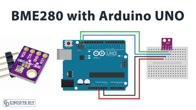 Interface BME280 Temperature, Humidity & Pressure Sensor with Arduino
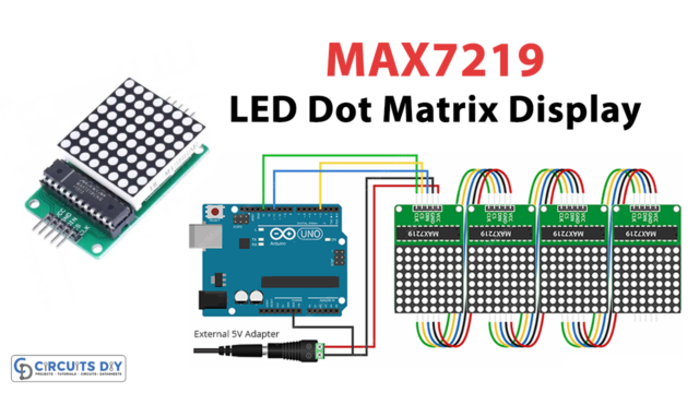 Interfacing MAX7219 LED Dot Matrix Display with Arduino UNO
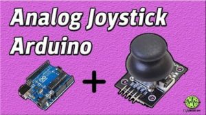 Analog Joystick with Arduino - Tutorial
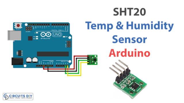 Interfacing SHT20 Temperature and Humidity Sensor with Arduino
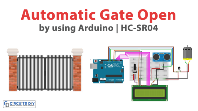 Automatic Gate Open Using Arduino and HC SR04


