Introduction:
By definition, a power supply is a device that converts the AC power from the mains to steady and precisely controlled DC power. Power supplies are the most common equipment used to provide electrical power to one or more electrical loads. It converts one form of electrical power to another, but may also convert the other form of energy (solar, mechanical, or chemical) into electrical energy. A laboratory power supply is a simple device that converts the AC power into smooth and constant DC power which is achieved by processing it through a few simple stages.
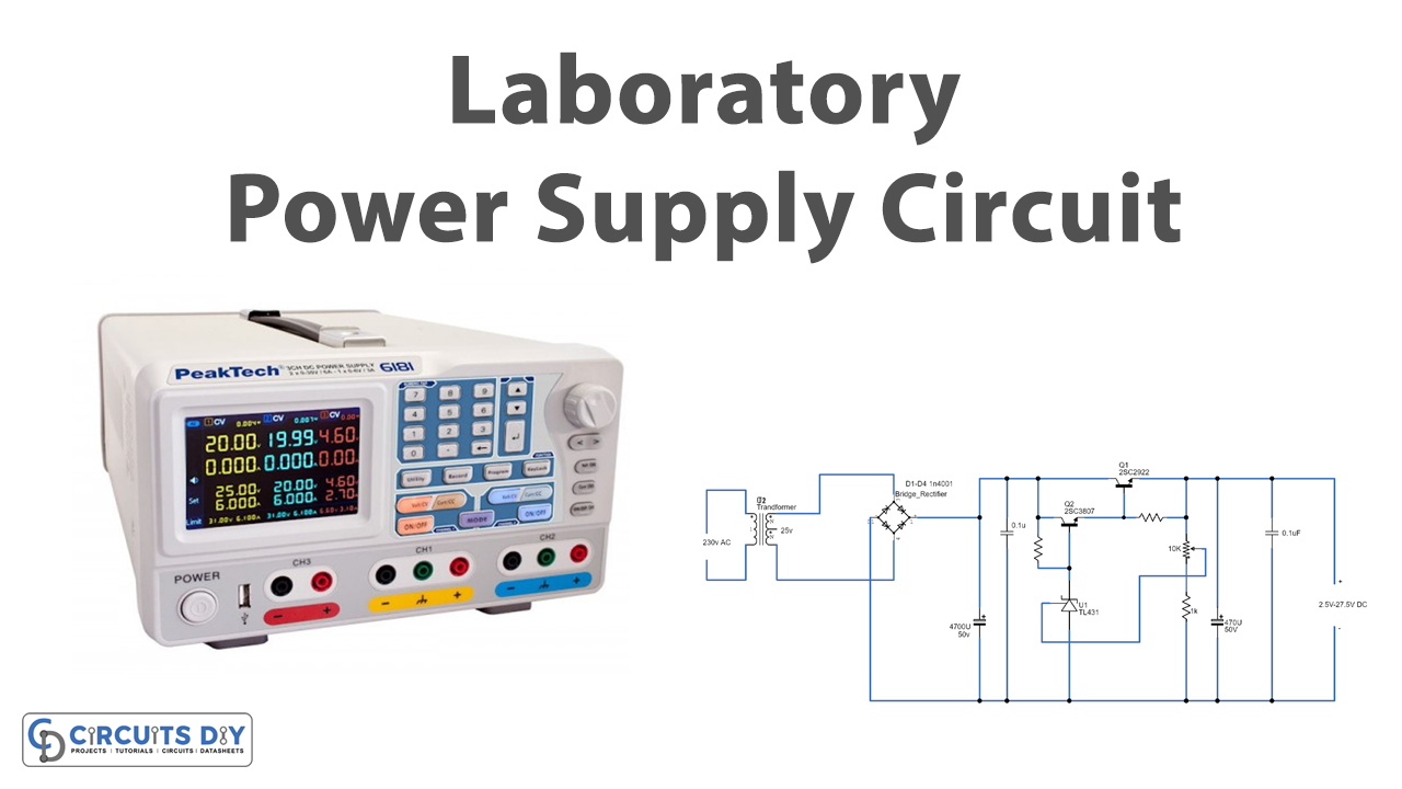
This post explains a simple, easy-to-build, pocket-friendly, and adjustable power supply which can be used as a laboratory power supply. It has an adjustable output range of 2.5V to 27.5V DC which is suitable for many applications. The circuit diagram and work are explained below.
Hardware Components
The following components are required to make Laboratory Power Supply Circuit
| S.no | Component | Value | Qty |
|---|---|---|---|
| 1. | Transformer | – | 1 |
| 2. | Diode | 1N4001 | 4 |
| 3. | Transistor | 2SC3807 | 1 |
| 4. | Transistor | 2SC2922 | 1 |
| 5. | IC | TL431 | 1 |
| 6. | Potentiometer | 10K | 2 |
| 7. | Ceramic Capacitor | 0.1uF | 1 |
| 8. | Electrolytic Capacitor | 470uF, 4700uF | 1, 2 |
| 9. | Resistor | 1K, 470 Ohms, 2K7 Ohms | 1, 1, 1 |
2SC2922 Pinout
2SC3807 Pinout
TL431 Pinout
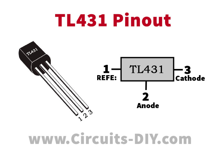
For a detailed description of pinout, dimension features, and specifications download the datasheet of TL431
Laboratory Power Supply Circuit
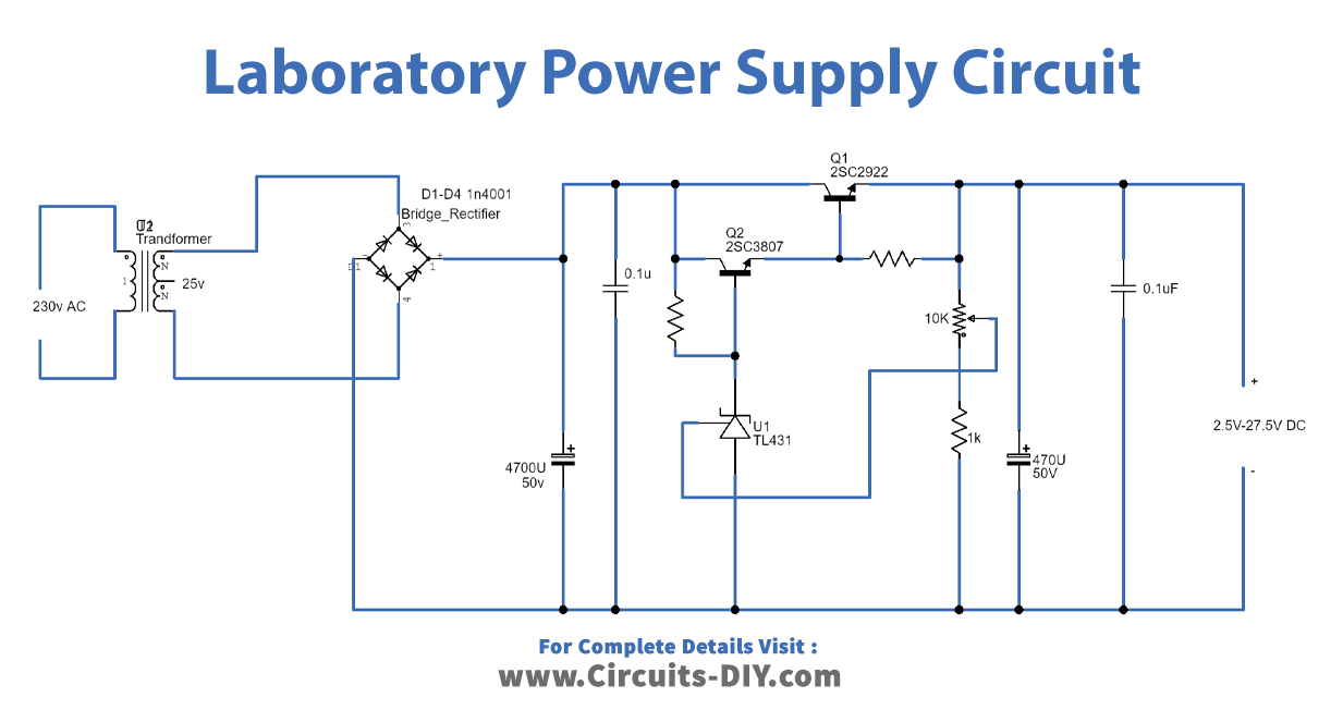
Working Explanation:
This simple circuit contains a transformer, bridge rectifier, capacitors, transistors (2SC2922 and 2SC3807), IC TL431, potentiometer, and resistors.
Transformer: The basic part of any power supply is the transformer which takes input from the electric power outlet. Its main function in the power supply is to step down the mains 230V AC power to 25V AC power.
Bridge Rectifier: The output of the transformer is fed into the rectifier which converts the stepped-down AC voltage into pulsating DC voltage which has a fixed polarity but its magnitude is a function of time. Rectifiers are built using diodes and resistors.
Filter: The output received from the rectifier is a pulsating DC voltage which must be filtered in order to achieve a non-pulsating DC signal which still can have some ripples or AC variations. The capacitors are generally used to perform filtering actions.
Regulator: The regulator circuit uses IC TL431, a potentiometer, and power transistors. It performs two functions:
- It eliminates the ripples from the non-pulsating DC signal received from the filter.
- It produces a constant voltage at the output which is not disturbed by the variation in the load or in the input voltage.
Applications & Uses:
Power supplies are the basic electronic instrument that finds their uses in different applications:
- Modern computers use power supplies to convert AC power into DC.
- Electric vehicles conserve energy generated through electrical generation and therefore they utilize power supplies to convert high voltage power from the vehicle battery.
- Various medical instruments need power supplies to operate.
- Avionics system also requires power supplies to convert power into usable power.
- Automation instruments such as conveyors, cameras, motors, pumps, assembly lines, etc. use power supplies for operating.