In this tutorial, we are going to make a “Lead Acid Battery Charger Circuit”.
To charge batteries, we need to put a voltage across the terminals, and the battery starts charging. The charging protocol depends on the size and type of the battery being charged. Some battery types have a high tolerance for overcharging and can be recharged by connection to a constant voltage source or a constant current source, depending on the battery type. If safe charging, fast charging, and/or maximum battery life are important, that’s when things get complicated. So here lead-acid battery is the most widely used rechargeable battery. Compared to modern rechargeable batteries, lead-acid batteries have relatively low energy density.
Despite this, their ability to supply high surge currents means that the cells have a relatively large power-to-weight ratio. These types of batteries provide electricity through a double sulfate chemical reaction. Simply active materials on the battery’s plates react with acid and provide electricity. By applying proper voltage and current we can easily Recharge Lead Acid batteries. By providing proper recharge cycle duration we can extend the life of Lead Acid batteries. We design a charger circuit based on IC LM317.
Hardware Components
The following components are required to make a Lead Acid Battery Charger Circuit
| S.no | Component | Value | Qty |
|---|---|---|---|
| 1. | Step down Transformer | 0-15V AC | 1 |
| 2. | Bridge Rectifier module | 1N4007 | 1 |
| 3. | Regulator IC | LM317 | 1 |
| 4. | Resistors | 1KΩ, 2.2KΩ, 220Ω, 1.8KΩ | 1,1,1,1 |
| 5. | Capacitor | 47µF/50V | 2 |
| 6. | LED | – | 1 |
| 7. | Schottky diode | MBR1545 | 2 |
| 8. | Switch | – | 1 |
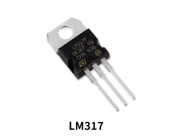
LM317 Pinout
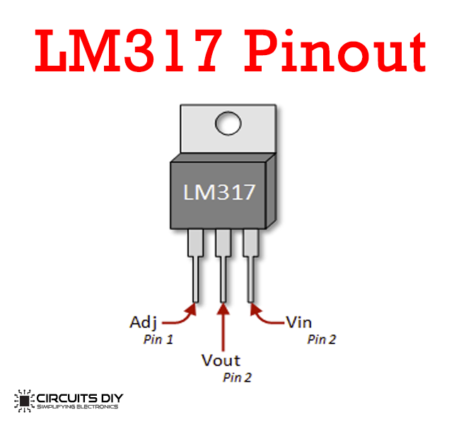
For a detailed description of pinout, dimension features, and specifications download the datasheet of LM317
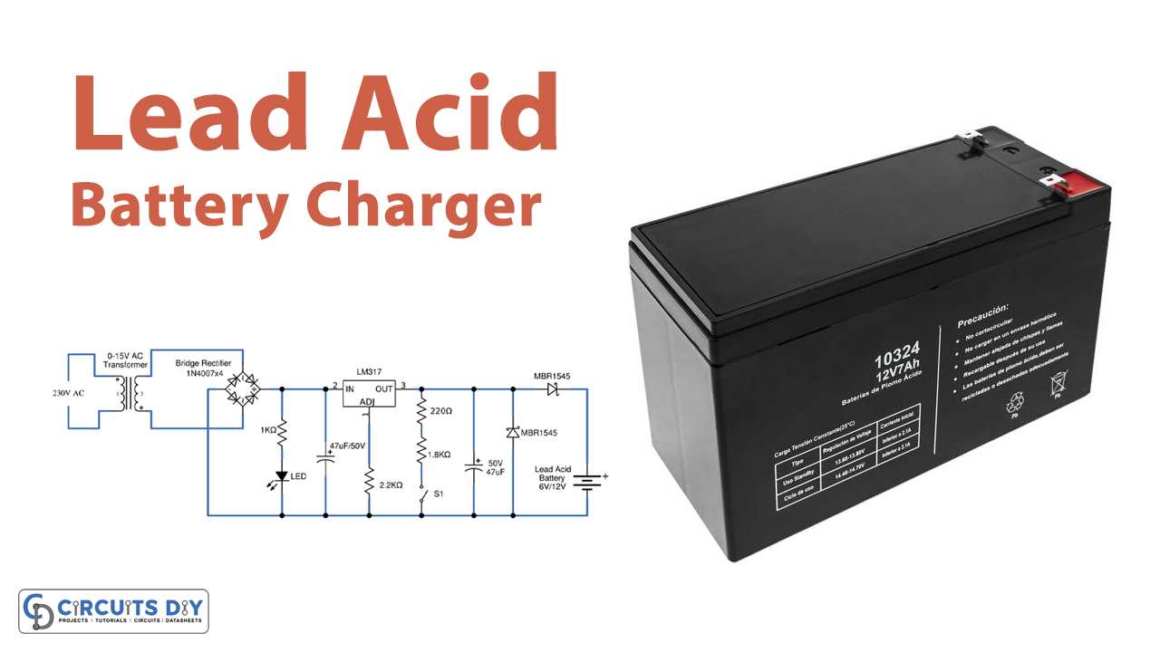
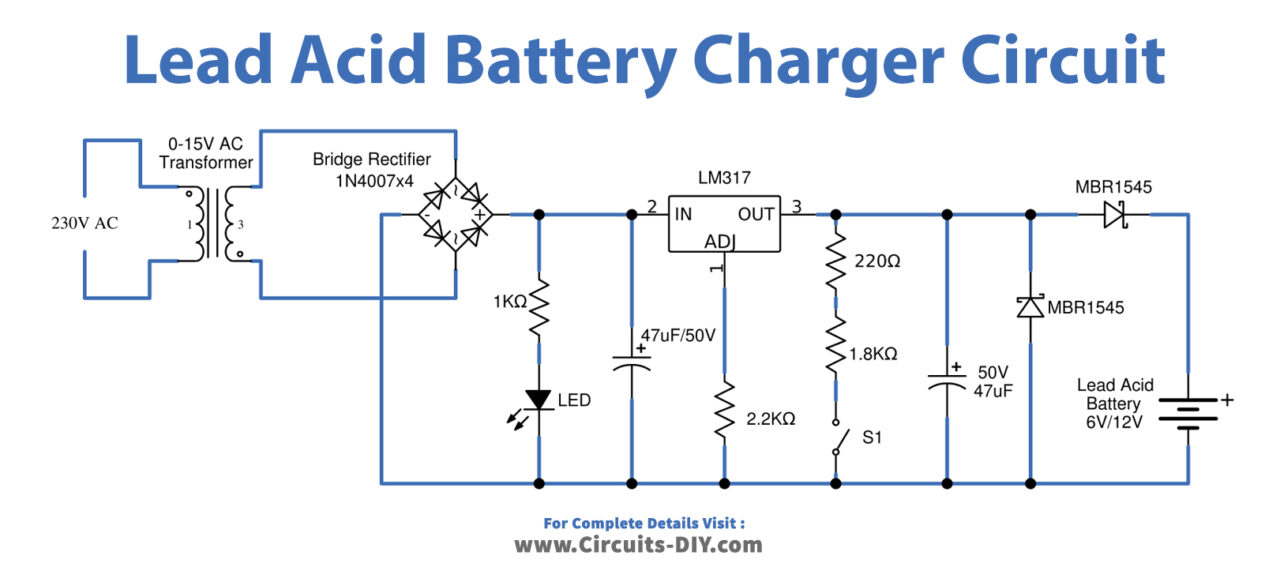
Lead Acid Battery Charger Circuit
Working Explanation
Here at first, we have a power supply section consisting of a 0–15-volt AC step-down transformer, this transformer is used to convert 230V AC supply into a 15V AC supply, a full-wave bridge rectifier comprising D1 through D4, which converts AC supply into DC supply and the smoothing capacitor C1, C1 performs filter process. Current regulation is achieved by the action of R1 and LED1. LED1 indicates the presence of DC supply and positive voltage Regulator LM317, which regulates the DC supply to the required level and by connecting R3, R4 Resistors with Adj pin this Regulator provides 6V output and disconnecting these resistors output will rise to 12V. Two SCHOTTKY rectifier diodes are connected at the output to protect the battery and circuit from reverse current and reverse polarity connections. By changing the switch only this circuit starts charging with about 1amp current. When you close SW1 for a little time, it can charge the battery to about 6V. 6V battery gives volt out about 7volt, this takes 10Ah time for charging. But when you open SW1 for enough time, it can charge the battery about 12V.
Which gives volt out about 14Volt. Lead Acid batteries require proper recharge and load circuits because they have a medium lifespan. If lead-acid battery plate active materials are dissolved then the battery will no longer sustain the recharge cycle which means the battery dies. Maintaining a Lead-Acid battery with a proper recharge circuit can extend the lifespan. This circuit is designed to charge a 6V and 12V battery and Switch S1 decides the output voltage.
Applications
Can be used in most handheld electronic devices.