Introduction
A fading LED potentiometer code on an Arduino UNO is a program written for the Arduino MCU that controls an LED using a potentiometer. The potentiometer is used as an input device, and the LED is used as an output device.
The code uses the Arduino’s analog input and digital output pins to read the position of the potentiometer and control the brightness of the LED. The MCU reads the analog value of the potentiometer using the analogRead function and maps it to a value between 0 and 255 using the map function. The mapped value is then used to control the brightness of the LED using the analogWrite function.
Hardware Components
You will require the following hardware for the fading of an LED with a potentiometer.
| S.no | Component | Value | Qty |
|---|---|---|---|
| 1. | Arduino UNO | – | 1 |
| 2. | USB Cable Type A to B | – | 1 |
| 3. | Potentiometer | – | 1 |
| 4. | 9V Power Adapter for Arduino | – | 1 |
| 5. | LED | – | 1 |
| 6. | Resistor | 220Ω | 1 |
| 7. | Breadboard | – | 1 |
| 8. | Jumper Wires | – | 1 |
Steps for Potentiometer fade LED with Arduino UNO
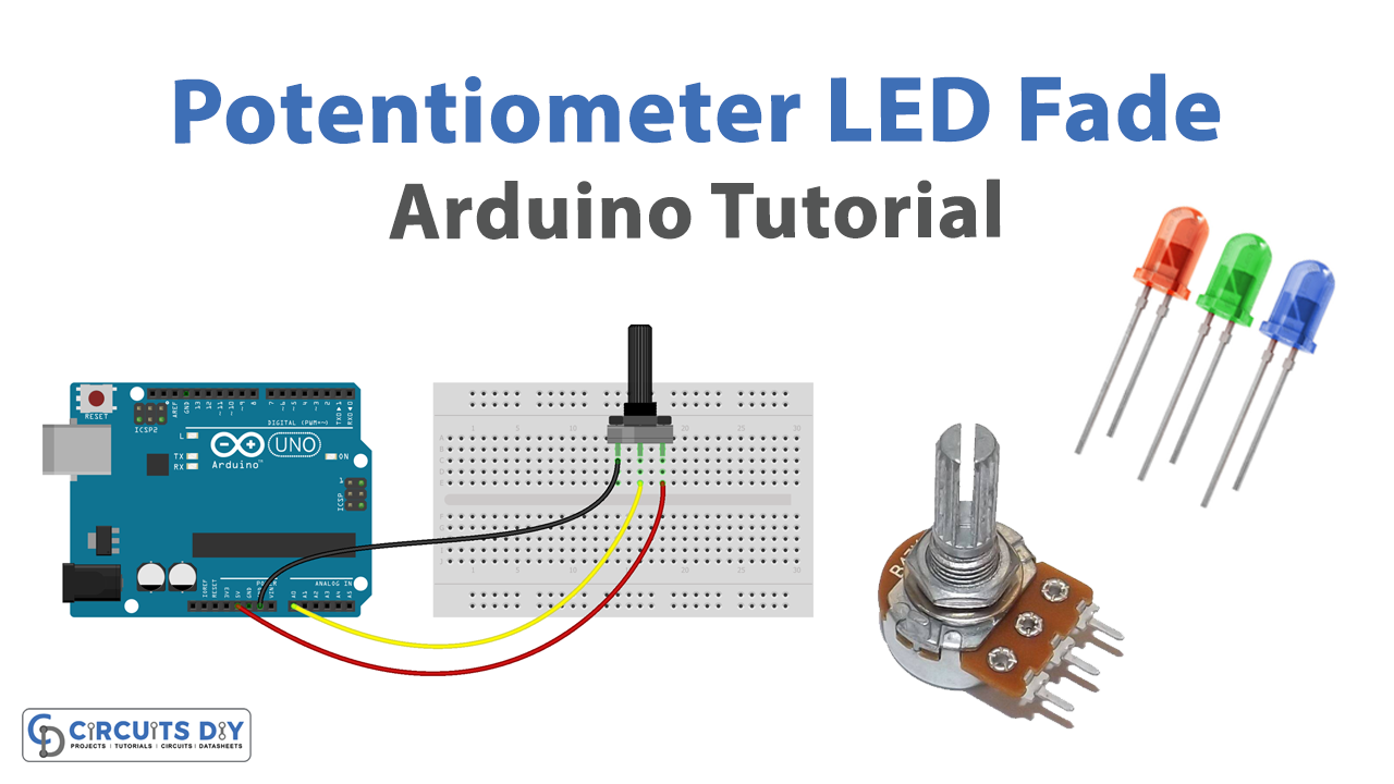
- Connect the LED to the breadboard. Connect the shorter leg of the LED to a row on the breadboard, and the longer leg to a different row. If you are using a 220-ohm resistor, connect it between the LED and the breadboard row as well.
- Connect the potentiometer to the breadboard. Connect one end of the potentiometer to a row on the breadboard and the other two ends to different rows.
- Connect the breadboard to the Arduino. Connect one end of a jumper wire to the row with the -ve of the LED and the other end to a digital output pin on the Arduino. Connect another jumper wire from the row with the longer leg of the LED to a ground pin on the Arduino. Connect one end of a jumper wire to the row with one end of the potentiometer and the other end to an analog input pin on the Arduino. Connect another jumper wire from the row with the other end of the potentiometer to a power supply pin on the Arduino.
- Open the Arduino software on your computer and create a new sketch by clicking “File” and then “New.”
- Set the pin mode for the digital output pin that the LED is connected to by adding the following line of code at the beginning of the sketch:
pinMode(ledPin, OUTPUT);Replace “ledPin” with the actual number of the digital output pin that the LED is connected to.
- In the loop function, add the following lines of code to fade the LED in and out based on the position of the potentiometer:
int sensorValue = analogRead(sensorPin);
int outputValue = map(sensorValue, 0, 1023, 0, 255);
analogWrite(ledPin, outputValue);
Replace “sensorPin” and “ledPin” with the actual numbers of the analog input and digital output pins that the potentiometer and LED are connected to.
- Upload the sketch to the Arduino board by clicking the “Upload” button in the Arduino software.
The LED should now fade in and out as you adjust the position of the potentiometer. You can modify the code to change the behavior of the LED, such as using a different range of values for the map function or using a different type of fading effect.
Schematic
Make connections according to the circuit diagram given below.

Installing Arduino IDE
First, you need to install Arduino IDE Software from its official website Arduino. Here is a simple step-by-step guide on “How to install Arduino IDE“.
Code
Now copy the following code and upload it to Arduino IDE Software.
int LED_PIN = 3;  // the PWM pin the LED is attached to

// the setup routine runs once when you press reset:
void setup() {
  // initialize serial communication at 9600 bits per second:
  Serial.begin(9600);

  // declare LED pin to be an output:
  pinMode(LED_PIN, OUTPUT);
}

// the loop routine runs over and over again forever:
void loop() {
  // reads the input on analog pin A0 (value between 0 and 1023)
  int analogValue = analogRead(A0);

  // scales it to brightness (value between 0 and 255)
  int brightness = map(analogValue, 0, 1023, 0, 255);

  // sets the brightness LED that connects to  pin 3
  analogWrite(LED_PIN, brightness);

  // print out the value
  Serial.print("Analog: ");
  Serial.print(analogValue);
  Serial.print(", Brightness: ");
  Serial.println(brightness);
  delay(100);
}
Working Explanation
The working of a potentiometer-controlled fading LED is very simple. In the setup function, the pin mode for the LED pin is set to OUTPUT using the pinMode function. This specifies that the LED pin will be used to output a digital signal to control the LED. In the loop function, the analog value of the potentiometer is read using the analogRead function. The analogRead function returns a value between 0 and 1023, representing the position of the potentiometer.
The analog value of the potentiometer is then mapped to a range of values using the map function. The map the function takes in a value, a range of input values, and a range of output values, and returns the mapped value. For example, if the potentiometer is at its minimum position, the analogRead function will return 0, and the map function can be used to map this value to a range of 0 to 255, which can be used to control the intensity of the LED using the analogWrite function.
Applications
- Simple control panel
- Interactive display
- Lighting control
- Educational tool
- Prototype development
- Art installation
Conclusion
We hope you have found this Potentiometer fade LED Circuit very useful. If you feel any difficulty in making it feel free to ask anything in the comment section.