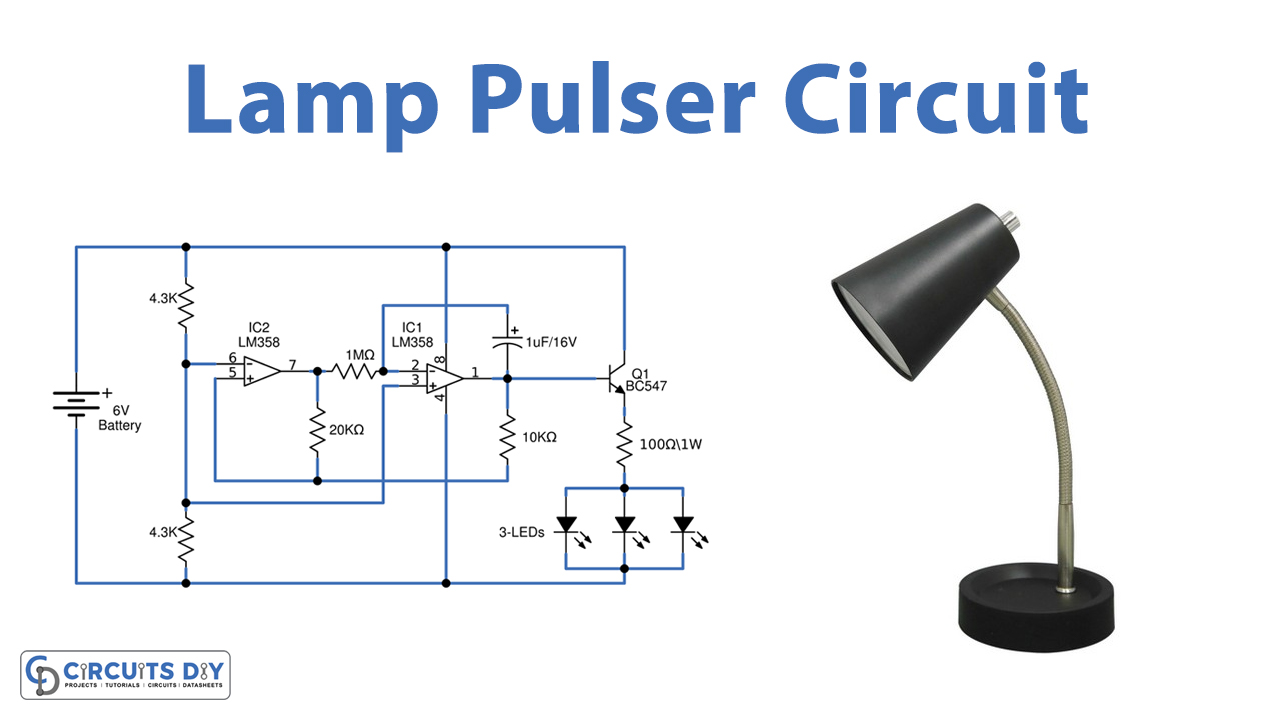
In this tutorial, we are going to make a “Lamp Pulser Circuit”.
This is a simple circuit that can be used to pulse an LED or a low-power filament lamp. As LEDs are used for decoration, we can add some effects to LED lighting and make it more attractive by using this simple circuit. The effect is such that the LED lights up from OFF state to ON state gradually then dims gradually to the OFF state.
The circuit is nothing but a triangular wave generator based on a dual operational amplifier LM358. The LM358 contains two independent high gain operational amplifiers, low power, dual-channel op-amp, and high gain with internal frequency compensation. A single power supply will be required to operate both op-amps in LM358. We can also use a split power supply. The device has a low power supply voltage.
Hardware Components
The following components are required to make Lamp Pulser Circuit
| S.no | Component | Value | Qty |
|---|---|---|---|
| 1. | IC | LM358 | 1 |
| 2. | Resistor | 4.3KΩ,1MΩ, 20KΩ, 10KΩ, 100Ω | 2,1,1,1,1 |
| 3. | Electrolyte Capacitor | 1µF/16V | 1 |
| 4. | Transistor | BC547 | 1 |
| 5. | LED | – | 3 |
| 6. | Connecting Wires | – | 1 |
| 7. | Power Supply | – | 1 |
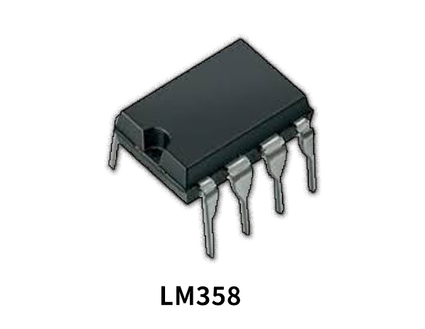
LM358 Pinout

For a detailed description of pinout, dimension features, and specifications download the datasheet of LM358
Lamp Pulser Circuit
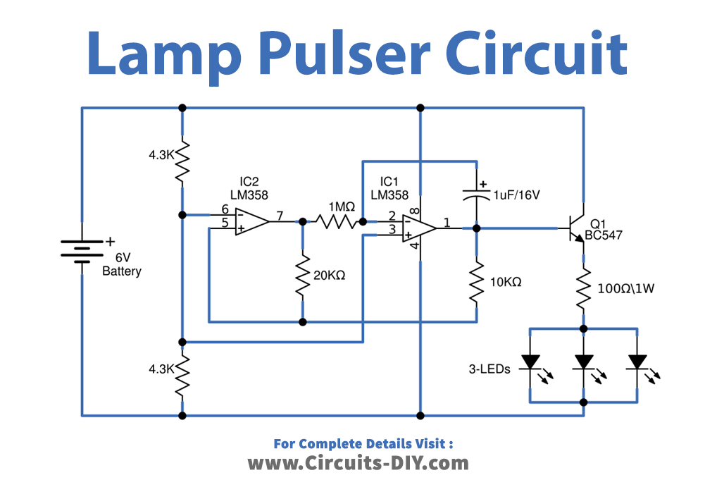
Working Explanation
This circuit consists of a dual operational amplifier IC LM358, as we can see voltage divider Resistor connects with IC1A via inverting pin 2 and with IC1B via Non inverting pin 5. C1 timing Capacitor connected as feedback to IC1B operational amplifier. The output of the IC1A operational amplifier is connected with the IC1B operational amplifier Inverting pin through timing Resistor R4, the timing components are C1 and R4 by changing the value of these two components we can get different frequency level output. Resistors R3 and R5 act as feedback Resistors for individual operational amplifiers. The transistor Q1 BC547 is used to drive the load (LED or lamp). Output from the IC1B is connected to the Q1 transistor base terminal and LEDs are connected at the Emitter terminal of Q1.
When we apply voltage to this circuit it will Oscillate triangular wave, which is depending on the timing elements value. Then LEDs are starts to Glow and dim gradually, and by adding a transistor driver and bias you can extend the number of LEDs.
Applications
This circuit can be used for decoration purposes in any event, function, or concert.