A music-reactive LED circuit is a simple electronic circuit that responds to varying sound levels, usually, of the rhythmic melody from nearby playing music & displays the changing intensity level of the sound signal in the form of blinking LEDs. It is a common circuit usually used for decorative purposes in places such as ceremonies, clubs & advertisements. So, in this project, we are going to design a simple Music Reactive LED circuit using an Arduino Nano Micro-controller.
The Arduino Nano Microcontroller is a tiny, reliable, durable, and breadboard-friendly Microcontroller board based on the ATmega328p model. On a functional scale, it is pretty much similar to the Duemilanove model, but in a slightly different package. It has no DC power jack like other models & requires a Mini-B USB cable to be powered by a laptop or PC.

JLCPCB is the foremost PCB prototype & manufacturing company in china, providing us with the best service we have ever experienced regarding (Quality, Price Service & Time).
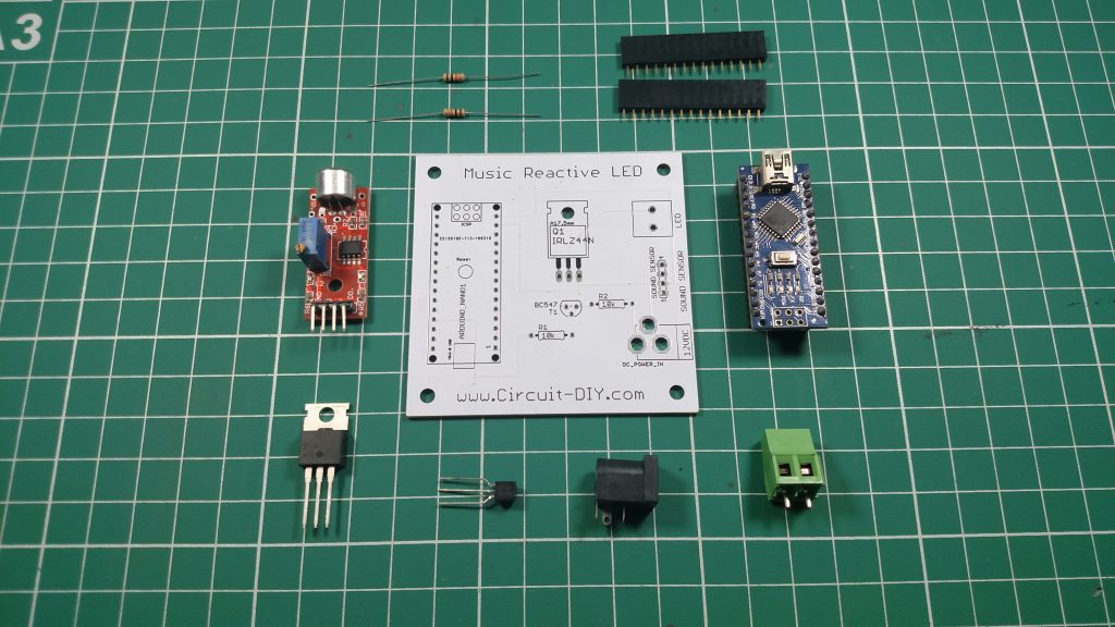
Hardware Components
You will need the following parts to build this project.
Useful Steps
Follow the steps as shown in the video above
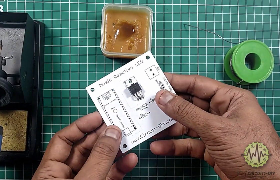
1) Solder the IRFZ44N transistor on the PCB Board.
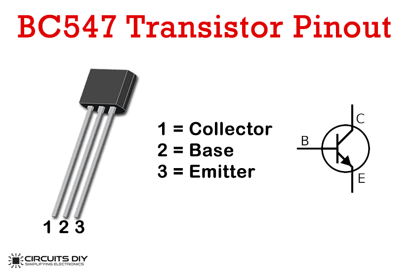
2) Solder the BC547 transistor & the 10K Ohm resistors on the PCB Board.

3) Solder the Female headers on the PCB Board.

4) Solder the Output Connector & the DC power jack on the PCB Board.

5) Connect the Arduino Nano Controller & the sound sensor module on the PCB board. After that, upload the source code to the Arduino

6) Testing & inspection.

Music Reactive LED Circuit Diagram

Working Explanation
The working of this circuit is pretty simple. An AC audio Signal is taken as input by the KY – 038 sound sensor module. The module feeds the analog out at pin A0 of the controller & the digital out to pin D8 of the microcontroller. Now to the working of the controller, D8 is defined as the sound sensor input while D9 is defined as the LED strip out using the pin Mode() command. Now, using the digital Read() command, each time the sound sensor detects a sound (status sensor == 1) it sets the pin D9 of the controller to high using Digital Write().
When D9 is set to high, the outDC signal acts as a control signal to the base of the BC547 transistor. The collector output of the transistor goes to the Gate of the IRFZ44N transistor. IRFZ44N is known for its high drain current and low switching time. It also has a low Rds value which will help in increasing the efficiency of switching circuits. The Drain output of the transistor then triggers the LED strip corresponding to the input sound signal.
Code
//Circuits DIY
//sound reactive light
int soundSensor = 8;  //define Sound Sensor Pin
int LED = 9;          //define LED Strip Pin

void setup()
{
  pinMode (soundSensor, INPUT); //define Sound Sensor as input
  pinMode (LED, OUTPUT);        //define LED Strip as output
}

void loop()
{
  int statusSensor = digitalRead (soundSensor);   //define variable of the Sound Sensor status
                                                  //and read value of the Sensor's

  if (statusSensor == 1)        //When the Sensor detects a signal
  {
    digitalWrite(LED, HIGH);    //LED Strip will be active
  }

  else                          //If no signal is detected
  {
    digitalWrite(LED, LOW);     //The status of the LED strip is deactivated
  }

}
Applications of Music-Reactive LED
- Usually seen in places such as nightclubs, ads & small electronic projects.