In this tutorial, we are going to make a “Double Tube Light Circuit Diagram”. One of the most difficult automotive repair tasks that a mechanic or repair shop can tell you, is the wiring or rewiring of a car’s electrical system. The difficulty in fact is that every car is different. Taking into account grating to remove, replace, or repair the Led Tube Light wiring in an automobile. As we know the tube light is a low-pressure mercury vapor gas discharge lamp. Also is known as fluorescent light, and mostly produces white light.
Nowadays CFL and LED lighting products are produced on a large scale, even though LED lights cannot replace tube lights thoroughly. The tube light gives smooth bright light, but till now LED can’t. Here we have made a double tube light connection by using a single ballast or choke (some electronic chokes do not support this connection). Check the ballast specification and watts level, before making this type of connection.
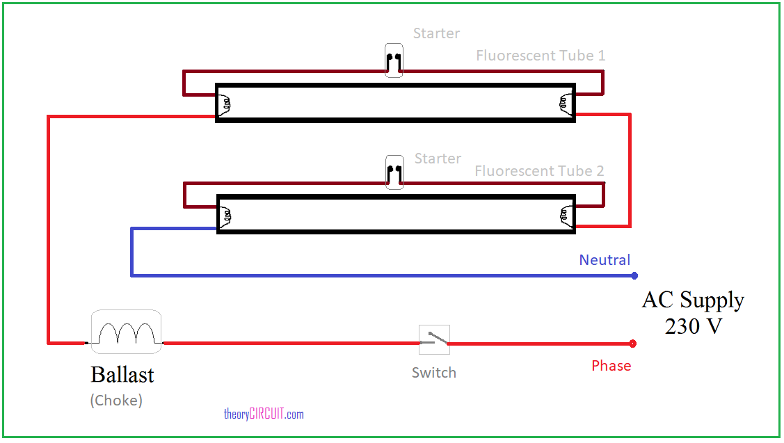
Wiring Diagram
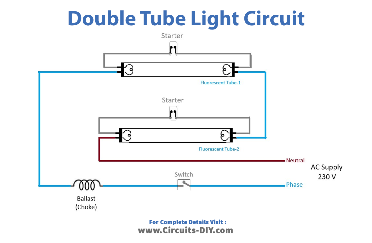
Here we have used two tube lights of 20 watts. Each tube light will have two filaments with four terminals, connecting the starter element to any one side of the tube light. And after that, link the phase line to the ballast (choke) through the switch. Now connect the other terminal of the Ballast to the terminal of the first tube light. Then connect tube light 2 with the first one serially, as shown in the illustration. Finally, bring the neutral terminal from tube light 2.
Starter

A starter is a control device, that is used for switching the equipment either manually or automatically. It is used for safe ON/OFF control of electrical equipment, by making or breaking its contacts. Here starter is placed parallel to the tube filament. It contains a small neon lamp-like setup with fixed contact, a bimetallic strip, and a small capacitor. The starter provides a current flow path to the filament of the tube at the initial time. It becomes inactive after the gas ionization and current flow in the tube.
Blast or choke

An electrical ballast (sometimes called control gear) is a device, intended to limit the amount of current flowing in an electric circuit. A choke is an inductor, designed to have a high reactance to a particular frequency when used in a signal-carrying circuit. Here this electric device produces high voltage by using low-frequency AC voltage. It helps the tube light mercury vapor gas to ionize. After ionizing, this ballast or choke reduces the output voltage level.
Applications
Due to their reduced price, the double tube CFL bulbs are used for various applications including corridors, security, general lighting purposes, and task lighting.


