Introduction
When there are so many difficult circuits out there in electronics that are also challenging to make, there are also a few circuits that are exciting to make. In electronic devices, we usually use LEDs for signs or indications. We always try to come up with different circuits, sometimes we try to build complicated circuits to make them simpler for you. While sometimes we implement fun circuits that can break your boredom. Hence, today In this tutorial, we are going to make an “LED flasher circuit”. If you are a complete beginner, this is one of the easiest circuits to kick start. The circuit uses the LM3 timer IC 3909 to generate oscillation and delays.
Hardware Required
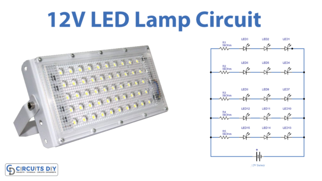
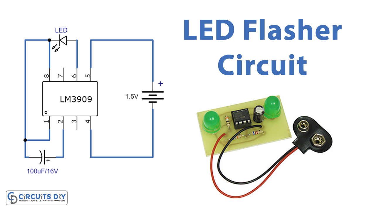
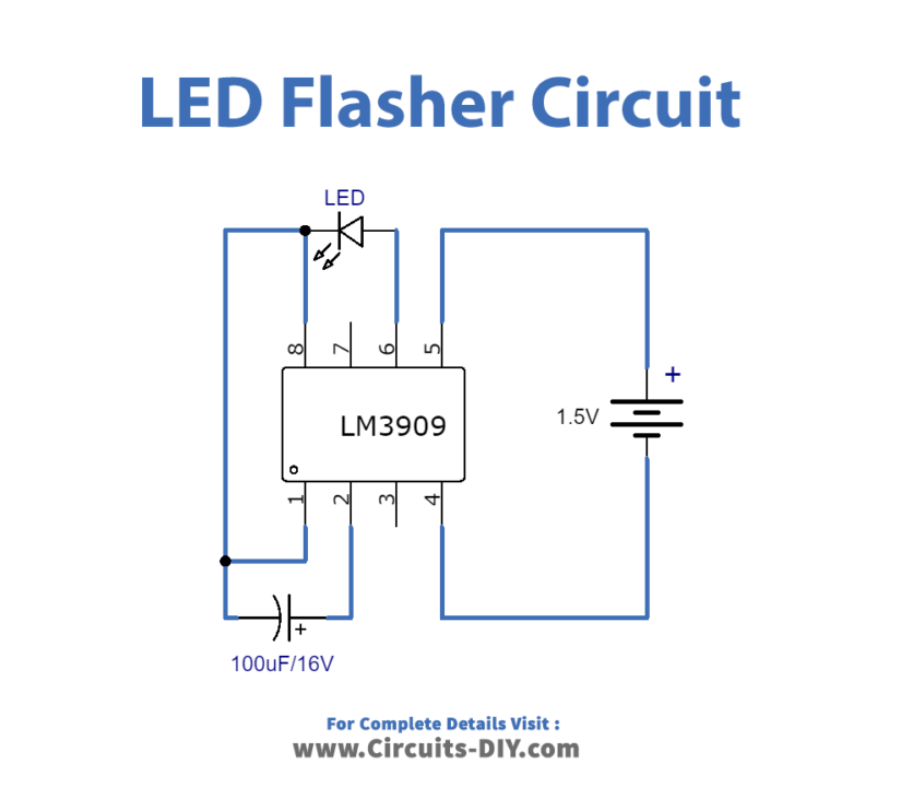
Circuit Diagram
Working Explanation
This LED flasher circuit is using an IC LM3909 which is a monolithic oscillator and is specially designed to flash Light-Emitting diodes. Here we are using a 100uf timing capacitor for voltage boost. At the supply of 1.5V or less, this timing capacitor will deliver pulses of two or more volts to the LED. The circuit is naturally self-starting. Hence only need a battery and capacitor to work as a flasher circuit.
Application and Uses
- In the circuits of vehicle indicators.
- In the making of LED blinking circuits.
- As a signal flashlight.
- Also, used for decoration purposes
- In toys of children.
- In signal lights.
- In some display circuits, etc.