In this tutorial, we are going to make an “LM35 Temperature Indicator LED circuit”.
Industries that do some temperature-specific work need good temperature sensing, monitoring, and control process. In simple applications, to indicate the temperature level we do not need to put complex circuits. Here we design an LM35 temperature indicator LED circuit without any microcontroller, only with a few components and it works to indicate whether the temperature is above or below the threshold. This circuit can work as a temperature indicator or it can trigger any device like a fan or alarm beyond a particular temperature. If you set the threshold temperature very high like 100 Degree Celsius it can also work as a fire alarm. So, to indicate the temperature threshold level we have two LEDs Green and Red. The level can be set by adjusting the Variable resistor RV1, and the 5V DC supply can be used to power the circuit.
Hardware Components
The following components are required to make Temperature Indicator LED Circuit
| S.no | Component | Value | Qty |
|---|---|---|---|
| 1. | Temperature Sensor | LM35 | 1 |
| 2. | Operational Amplifier IC | MC1458 | 1 |
| 3. | Transistor | BC547 | 2 |
| 4. | LED | – | 1,1 |
| 5. | Variable Resistor | 10KΩ | 1 |
| 6. | Resistor | 8.2KΩ,10KΩ,680Ω | 1,1,3 |
| 7. | Connecting Wires | – | – |
| 8. | Battery | 5V | 1 |
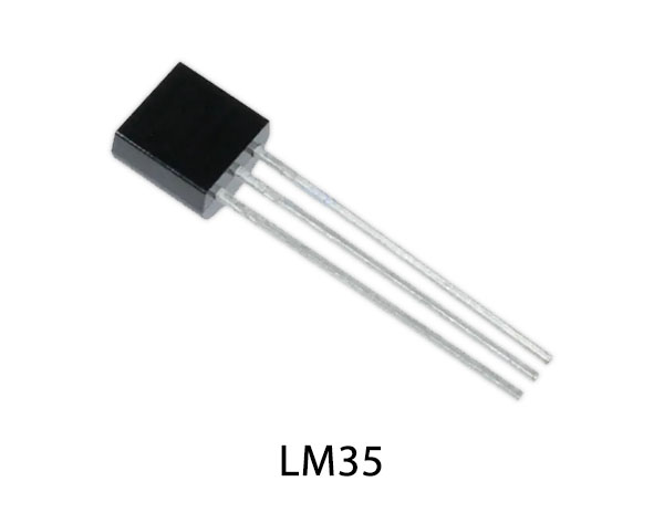
LM35 Pinout

For a detailed description of pinout, dimension features, and specifications download the datasheet of LM35
MC1458 Pinout

For a detailed description of pinout, dimension features, and specifications download the datasheet of MC1458
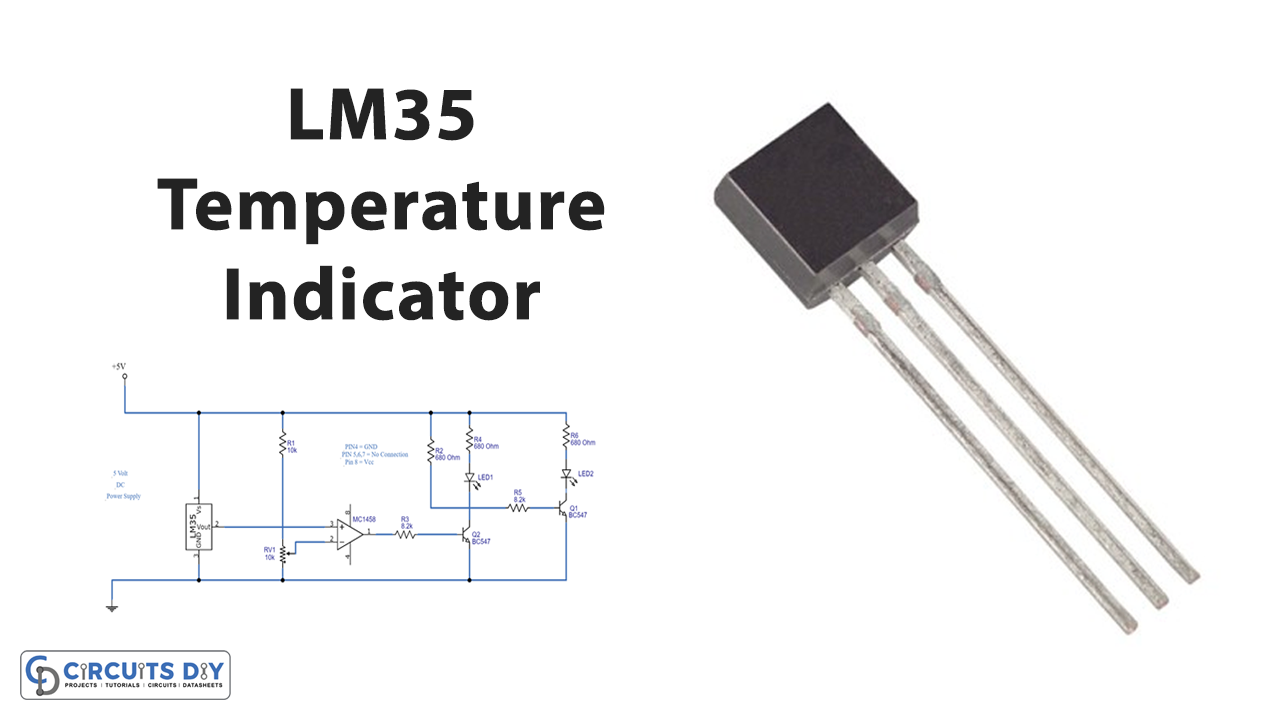
Temperature Indicator LED Circuit

Working Explanation
To make this circuit, we need a general-purpose operational amplifier MC1458 and temperature sensor LM35 and proper biasing of both components. Here connect the LM35 sensor output to the operational amplifier non-inverting input pin, Inverting pin of the operational amplifier should be connected with the variable resistor to set the temperature threshold level. Now connect the output of MC1458 to the Q1 transistor base through the R3 resistor and the collector terminal of Q1 is connected to the Q2 transistor base through R5 Resistor. Here LED Red is connected with the Q1 collector and LED Green is connected with the Q2 collector terminal through 680Ω Resistors.
When the surrounding temperature goes above the threshold level output voltage of LM35 at pin 2 also goes higher and the output of LM35 is connected to Pin 3 of MC1458, which generates output, and Q1 becomes turned ON and makes the red LED glow and the Q2 transistor won’t get bias so it becomes turned OFF. MC1458 doesn’t generate output if the temperature is below the threshold level so the Q1 transistor becomes turned OFF and the Q2 transistor base gets supplied through the R2 resistor and makes the LED green glow.
Applications
- Measuring the temperature of an environment.
- Monitoring Battery temperature.
- Providing thermal shut down for a system when required.