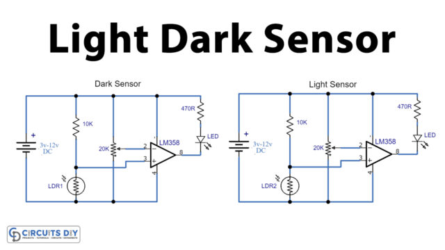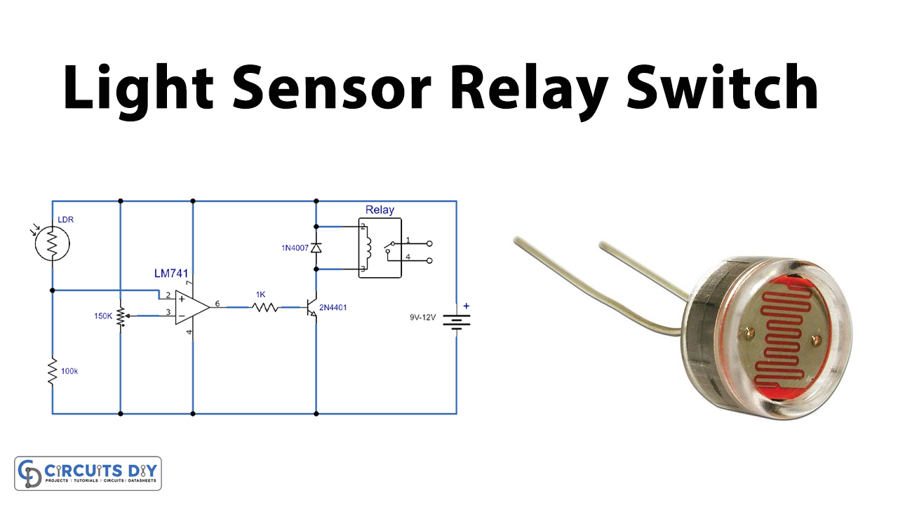
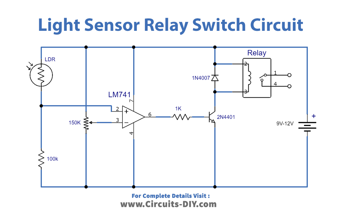
A light-sensing relay switch in a wide variety of renewable energy projects is extremely useful and flexible, from automatic lighting to protection systems. The diagram below shows the proper figure of the LM741 light sensor relay switches circuit project/schematic. The circuit is pretty sensitive and activates the relay when a small amount of light falls on the LDR board.
In our article Light-Based Resistor we explained how an LDR can be used to monitor devices according to the ambient lighting rates in simple circuits – for example, automatically making a lamp turn on above a doorway at night.
Hardware Components
The following components are required to make Light Sensor Relay Switch Circuit
| S.no | Component | Value | Qty |
|---|---|---|---|
| 1. | Resistors | 100K, 1K | 1, 1 |
| 2. | Potentiometer | 150K | 1 |
| 3. | IC | LM741 | 1 |
| 4. | Transistor | 2N4401 | 1 |
| 5. | Diode | 1N4007 | 1 |
| 6. | Relay | – | 1 |
| 7. | LDR | – | 1 |
| 8. | DC Supply | 9-12V | 1 |
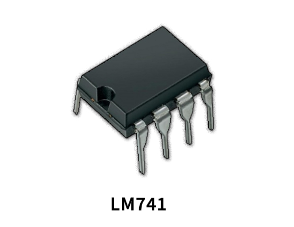
LM741 Pinout

For a detailed description of pinout, dimension features, and specifications download the datasheet of LM741
Light Sensor Relay Switch Circuit
Working Explanation
LM741 is a renowned working amplifier IC. Electronic programs are varied It can be built using this IC, making the IC very popular among electronic amateurs, experimenters, it hobbyists. The IC is relatively old but still well-known There are also better models of practical amplifiers nowadays available which are also gaining popularity, such as TL071. The circuit is very basic, and only a few external components are used. With a 150K variable resistor, the circuit’s sensitivity can be changed. The IC’s output current is 25mA, which means that the relay cannot be directly controlled with the IC, so we controlled it via a 2N4401 NPN transistor.
Application and Uses
- A light-sensing relay switch is extremely useful and flexible for a wide range of renewable energy projects, from automatic illumination to safety systems