Some types of electronic equipment do not provide any indication that they are actually on when they are switched on. This situation can occur when the backlight of a display is switched off. In addition, the otherwise mandatory mains power indicator is not required with equipment that consumes less than 10 watts. As a result, you can easily forget to switch off such equipment. If you want to know whether the equipment is still drawing power from the AC outlet, or if you want to have an indication that the equipment is switched on without having to modify the equipment.
Many times we are checking about the presence of a power supply through neon indicators on the supply board when there is no option to know the status of the power supply means we need to use a tester or multimeter. Here for this, we design a simple circuit with easily available components, it provides the status of the presence of the main power supply through visual and audible output.
Hardware Required
| S.no | Component | Value | Qty |
|---|---|---|---|
| 1. | AC Power Supply Connector | 230v | 1 |
| 2. | Zener Diode | 12V | 1 |
| 3. | Diode | 1N4007 | 1 |
| 4. | Resistor | 100KΩ,1KΩ | 1,1 |
| 5. | LED | – | 1 |
| 6. | Capacitor | 1uF/400V,100uF/25V | 1,1 |
| 7. | Connecting Wires | – | – |
| 8. | Buzzer | – | 1 |
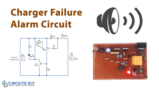
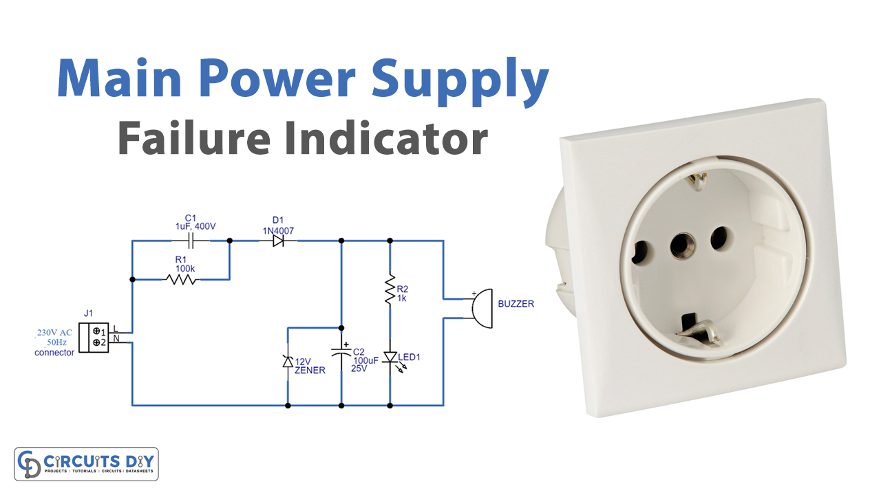
Circuit Diagram
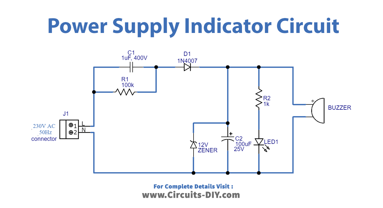
Construction and Working
As we can see, the LED and buzzer are used in this circuit to indicate the main power supply status. The circuit is built around capacitors C1 and C2, resistors R1 and R2, diode D1, Zener diode ZD1, LED1, and a piezo buzzer (PZ1). Resistor R1 and capacitor C1 are used for reducing the voltage and limiting the current. Diode D1 is a rectifier. C2 is used as a filtering capacitor. Zener diode ZD1 limits the output voltage to around 12V. The value of the Zener diode should be equal to or lower than the maximum voltage of the buzzer and higher than the minimum voltage. Here when 230v AC power supply passed through C1 and R1 components and rectified through the D1 diode. And then regulated by a ZD1 Zener diode, this regulated power supply is given to the LED and buzzer. The buzzer should have a built-in oscillator working in the range of 6V-12V and requiring a current below 10mA. The frequency of the alarm sound is usually several kilohertz (kHz).
LED1 is on when the mains power supply is present, and at the same time, the buzzer produces sound. Resistor R1, capacitor C1, and diode D1 are selected depending on the current requirement of the buzzer. Take extra care when dealing with high AC voltage.
Applications
Can be used in homes and workplaces.