Introduction
Grounding is considered one of the major elements in the designing of printed circuit boards. It allows to pass the signal clearly and move the data forward. Thus, designers cannot ignore the place of grounding in their designs, it may cause trouble. If a designer cannot focus on grounding currents, it may question the reliability of the PCB. Therefore, in this article, we share the best-printed circuit board grounding techniques. But, before this, you must have to understand the ground and the grounding.
What is Ground?
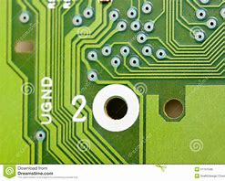
Basically, the ground is the common path that returns the flow of current. Moreover, works as the reference point that allows the measurement of the voltage across different parts and components of the circuit. Hence, it occupies a major portion of the printed circuit boards. Also, poor grounds can create problems in the circuit. For example, signal coupling, noise interference, and ground loops can happen because of improper grounds. Hence, this may affect the performance and durability of PCB.
Types of Grounds

There are some different types of grounds. Essentially these are the nods that are referred to as the grounds.
- Earth Grounds: This is a physical connection to the earth. A safe return path to drain current.
- Chassis Ground: When there is a metal chassis that acts as the ground. This is utilized for safety purposes and as an enclosure body.
- Floating Grounds: A ground that is not bodily connected to the earth. It’s basically a great reference conductor that acts as the ground.
- AC Grounds: An AC ground is the low impedance ground path that blocks the DC.
- Virtual Grounds: These grounds are practiced in negative feedback circuits at the inverting end of opamps.
Grounding Techniques
The most common question that new designers asked for is the grounding tips or the techniques, Proper grounding techniques can ensure noise-free and clean signals. So, here are some printed circuit board grounding techniques that can save the life of the new designers.
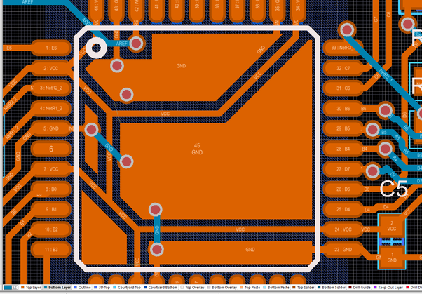
Ground Planes: Use the ground plane. It refers to the plane of the copper that carries a current that has to be returned at different points of the printed circuit boards. Also, this serves as the heat sink that lowers the impedance of the entire board. Mostly the bottom layers are used as the ground planes.
Ground Connectors: The high impedance in the circuit can cause oscillations in the current. To avoid high impedance, utilize more ground connectors. This can evade the greater impedance that can occur while connecting the PCB to another Board.
Ground Vias: Vias ensure to reduce the ground loops in the printed circuit boards. Hence, provides a more exact return path for the current to flow. Also, it serves to access the ground plane anywhere on the PCB.
Decoupling Capacitors: Connect decoupling capacitors from power trace to ground trace. It ensures eliminates the noise that can occur between the ground and power traces. Also, it can provide stable power to the integrated circuits that may be wired on the printed circuit board. Also, it reduces EMI interference on the board.
Related posts:
 6 Tips to Reduce PCB Size for Your Projects
 SMD Components | Commonly Used SMD Parts And Their Identification
 Reduce PCB Printing Cost | Top 5 Tips to Cut Cost During PCB Assembly
 Steps to Design Printed Circuit Board from JLCPCB
 Mistakes in Making of Printed Circuit Boards
 Printed Circuit Boards for Wireless Products


