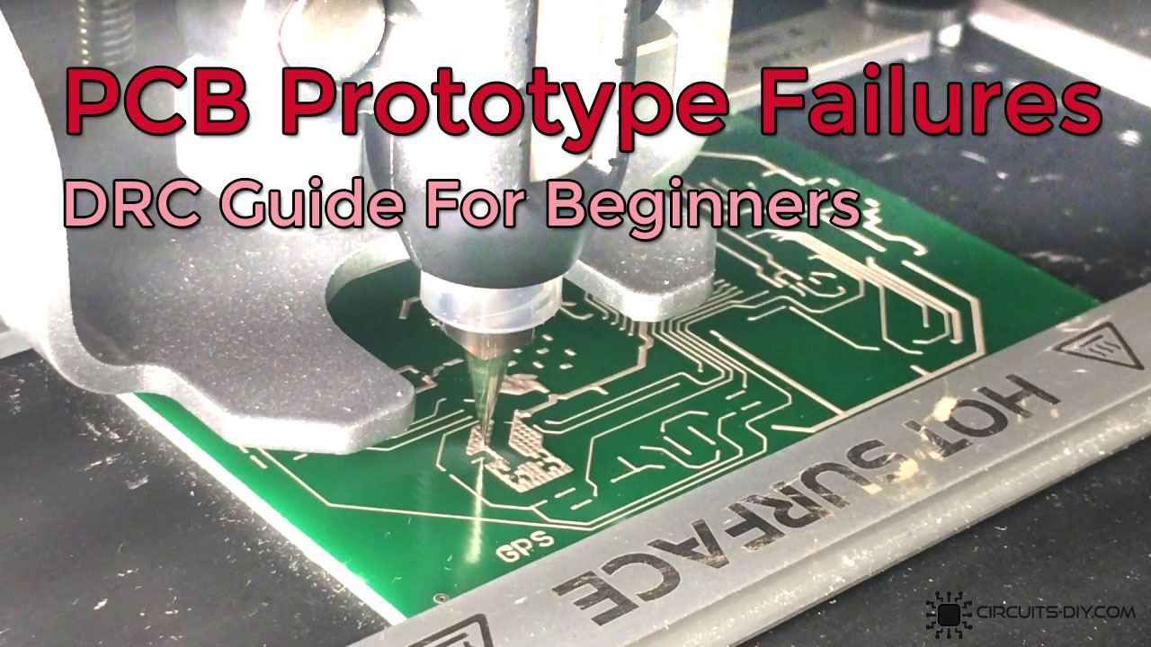
A DRC (Design Rule Checking) ensures that the submitted design complies with its published standard. Ensuring that the PCB will be fabricated conforming to a certain standard or spec. If there are any mismatches, the DRC points them out and the designer then updates the design/layout accordingly. DRC (Design Rule Checking) is a must to ensure there are no design violations in the PCB. This check is done prior to the manufacturing of the final board. In today’s article, we will discuss various ways we can be reducing PCB Prototype Failure Using Design Rule Check (DRC).
Design Rule Check (DRC)
Design rule is a geometric constraint set by a design engineer on the standards to which any circuit board, semiconductor device, and integrated circuit (IC) designer has to conform, in order to to ensure that their designs function properly, reliably, and can be produced with an acceptable yield. DRC checking is an essential part of the physical design flow and ensures the design meets manufacturing requirements and will not result in a chip failure. The process technology rules are provided by process engineers and/or fabrication facility.

Reducing PCB Prototype Failure Using Design Rule Check (DRC)
There are a number of design rule parameters, conforming to which on a collective basis helps in reducing PCB prototype failure.
1) Minimum Spacing
One of the many parameters covered by a DRC check is the minimum spacing present between the on board components. DRC also ensures that the spacing between the traces, trace, and pads, trace and through holes, pads, and holes, and also the space between the through-holes are reasonable or not. Can the space design fit the production or not.

2) Minimum Width
DRC check also determines whether the width of the VCC and GND lines conform with the PCB design parameters. Also, it checks if there is a tight coupling between the power supply and the ground wire or If any GND line traces need to be wider on the PCB board.

3) Minimum Area
DRC runs also check whether the overall size of the board as well as that of each component conforms with the total allowable area for the board and notifies if the board layout goes outside the defined PCB board outline.

4) Silkscreen Shorts
A DRC check also determines whether the labels and Icons added on the PCB board will cause any electrical shorts and notifies the designer to make changes accordingly.
5) Analog & Digital GNDs
DRC rule check also determines whether all the digital and analog circuits present on board have separate grounds.

6) Misaligned Via wire
DRC also checks whether two different layers of the same logical net have an aligned Via connection. If the inserted via is not aligning with the metal crossing the DRC check raises a VIA misalignment flag.

7) End of Line Spacing
Another design parameter that a DRC check determines is whether the outer rim of the power layer in a multi-layer PCB board is reduced to a desirable standard or not, for example, it is easy to cause short – circuits in multi-layer PCBA if the copper foil of the power layer is exposed.