Introduction
In some of our articles and tutorials, we have discussed and made different types of amplifiers, including preamplifiers. A preamplifier circuit is a type of electronic circuit that converts a poor audio signal into a strong signal. Alternatively, it boosts a call to action to the required level. It acts as a channel between a signal source and a power amplifier So, here in this tutorial, we are going to make a “Simple FET Preamplifier circuit (Very high impedance)”.
In the making of the circuit, we are using FET. A Field Effect Transistor (FET) is a semiconductor device with three terminals. It works by using a controlled input voltage. JFETs and bipolar transistors appear very similar. However, the BJT is a current-controlled device, whereas the JFET is voltage-controlled.
Hardware Required
| S.no | Component | Value | Qty |
|---|---|---|---|
| 1. | N-Channel Transistor | 2N3819 | 1 |
| 2 | Resistor | 2.2M, 1K, 1.8K, 100 ohms | 1, 1, 1, 1 |
| 3. | Electrolyte Capacitor | 10uF, 100uF | 1, 1 |
| 4. | Ceramic Capacitor | 0.1uF | 1 |
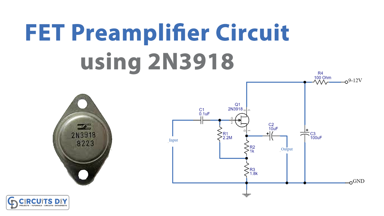
Circuit Diagram

Working Explanation
The above diagram depicts a field-effect transistor (FET) circuit. First and foremost, the DC power supply is powered by a decoupling system comprised of Resistor R4, and capacitor C3. The positive voltage is then applied to the drain (D), but the gate (G) demands Bias as a negative electric potential. About 3 volts is the constant voltage across R3. While the transistor’s emitter pins typically correspond to half of the power supply,
R1 and the gate are connected in a manner called bootstrapping systems with built-in positive feedback. Increasing the resistance’s efficiency causes this circuit’s input impedance to rise. And, hence, the output impedance is around 500 ohms when the signal is present.
Application Uses
- Amplifier circuits that require high impedance.
- This FET preamplifier circuit is appropriate for transmitting signals from the preamplifier to the amplifier circuit via longer wirings.