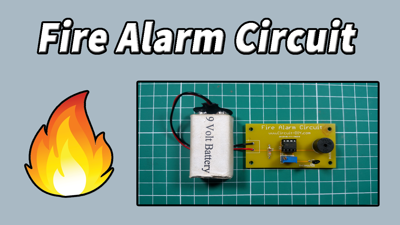
Fire Alarm Circuit is one of the simple and cool projects in electronics it detects the fire using a thermistor and activates the alarming sound with a buzzer. Fire Alarms have important practical applications in industries where it is necessary to detect fire at right time and prevent damage to people or property.
Fire Alarms & Smoke Sensors are mostly used in security systems its application is not only restricted to industries but also commercial buildings, offices, movie theatres, shopping malls, and other public places.
Hardware Components
The following components are required to make a Fire Alarm Circuit
| S. No | Component | Value | Qty |
|---|---|---|---|
| 1. | PCB | – | 1 |
| 2. | Thermistor | 10k | 1 |
| 3. | Trimmer Pot | 10k | 1 |
| 4. | Resistor | 10k | 1 |
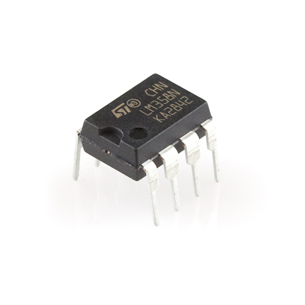
| 5. | IC | LM358 | 1 |
| 6. | Battery | 9v | 1 |
| 7. | Buzzer | – | 1 |
LM358 Pinout

For a detailed description of pinout, dimension features, and specifications download the datasheet of LM358N IC
Fire Alarm Circuit Diagram

Working Explanation
The fire Alarm circuit working is simple here we used a 10k NTC Thermistor to detect the fire and an LM358 Operational amplifier in comparator mode. What the thermistor does is when the temperature of the room OR area increases it decreases the resistance and as we look at the circuit diagram it is connected as a voltage divider to non-inverting input so its value is more than the inverting input hence the output of comparator becomes high and it activates the alarming sound.