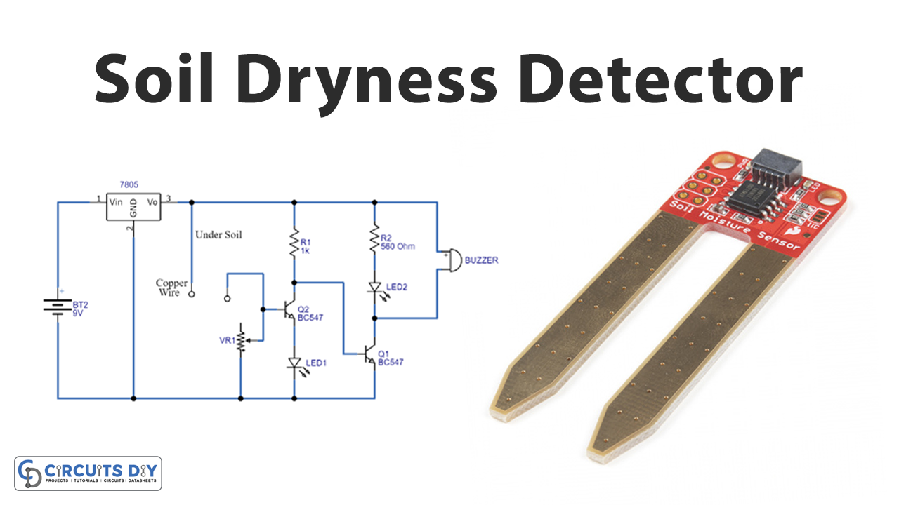
In this tutorial, we are going to make a “Simple Soil Dryness Detector Circuit”.
Soil is the most important natural gift after water and sunlight that this planet has provided us, without which the persistence of living beings could never be possible. As soil produces plants, plants supply us with food. However, plants need well-watered soil. Because the important thing for plant growth and life is water for proper plant hydration, we need to pour water regularly when the soil gets dry.
So, there’s a very obvious and direct use for measurements of soil moisture. It allows the need for irrigation to be quantified in advance of a crop showing signs of distress. Knowing the soil moisture status enables highly efficient irrigation, providing the water as and when required, and eliminating the wasteful use of water when irrigation is not needed. We design a simple Soil dryness detector circuit that employs two NPN transistors as a switch and a buzzer element to produce a beep sound when there is no water on the soil. Here is a sensor, we use insulation-removed copper wires or you can use conducting material nails as moisture-detecting sensors. This simple circuit helps you to identify the dryness of water in your plant soil or where ever needed.
Hardware Required
| S.no | Component | Value | Qty |
|---|---|---|---|
| 1. | Regulator IC | LM7805 | 1 |
| 2. | Conducting Copper Wire (or) Nail | – | 1 |
| 3. | Variable Resistor | 100KΩ | 1 |
| 4. | Resistors | 1KΩ, 560Ω | 1,1 |
| 5. | NPN Transistor | BC547 | 2 |
| 6. | LED | – | 2 |
| 7. | Buzzer | – | 1 |
| 8. | Connecting Wires | – | – |
| 9. | Battery | 9V | 1 |
Circuit Diagram
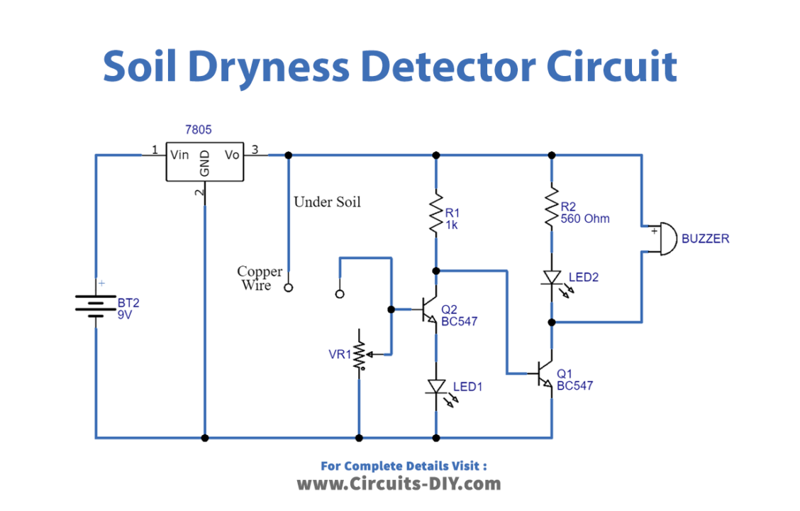
Working Explanation
This Soil Moisture Detector Circuit is very simple. As shown in the circuit, we have used a soil moisture detector probe which is two insulation removed copper wires to sense the moisture in the soil (you need to put those detectors in the soil up to your detection range. Don’t put copper wire or nails too near it may come to contact each other). Two NPN transistors trigger the buzzer and LED. Buzzer and LED are used as an indication of soil moisture detection. And Regulator IC 7805 to regulate 9V battery supply. Now when there is no moisture in the soil the probes do not allow 7805 to supply any voltage so the LED and Buzzer remain turned off. Now, whenever both probes will come in contact with soil moisture or water then both probe gets shorted because water/moisture is the conductor of current. And when probes get shorted then the base of the transistor gets connected to the output of 7805 IC.
When regulated 5V is applied to the transistor switches and the soil moisture detector setup (sensor). One terminal from the sensor is applied to the Q1 transistor base by which you can vary the sensitivity level by using RV1. So, when there is moisture in the soil then Q1 becomes turned ON due to the positive supply flow-through sensor to the base, if the soil is dry then Q1 stays in the turn-OFF position and all bias through the Q1 collector flows to the Q2 base terminal and Q2 gets turn ON and makes buzzer to produce beep sound. In the end, Green LED indicates enough moisture in the soil, and Red LED indicates dryness in the soil.
Applications
This Soil moisture sensor circuit can be used in many applications like systems, Greenhouse projects, etc.